Storm Drainage Utilities
-
font size
decrease font size
 increase font size
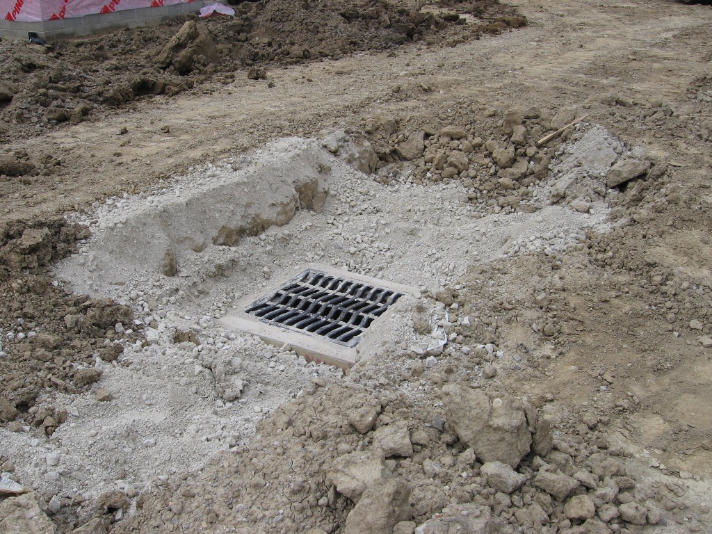
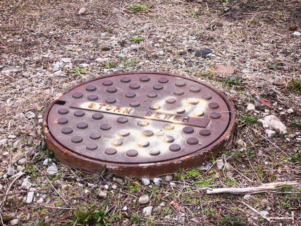
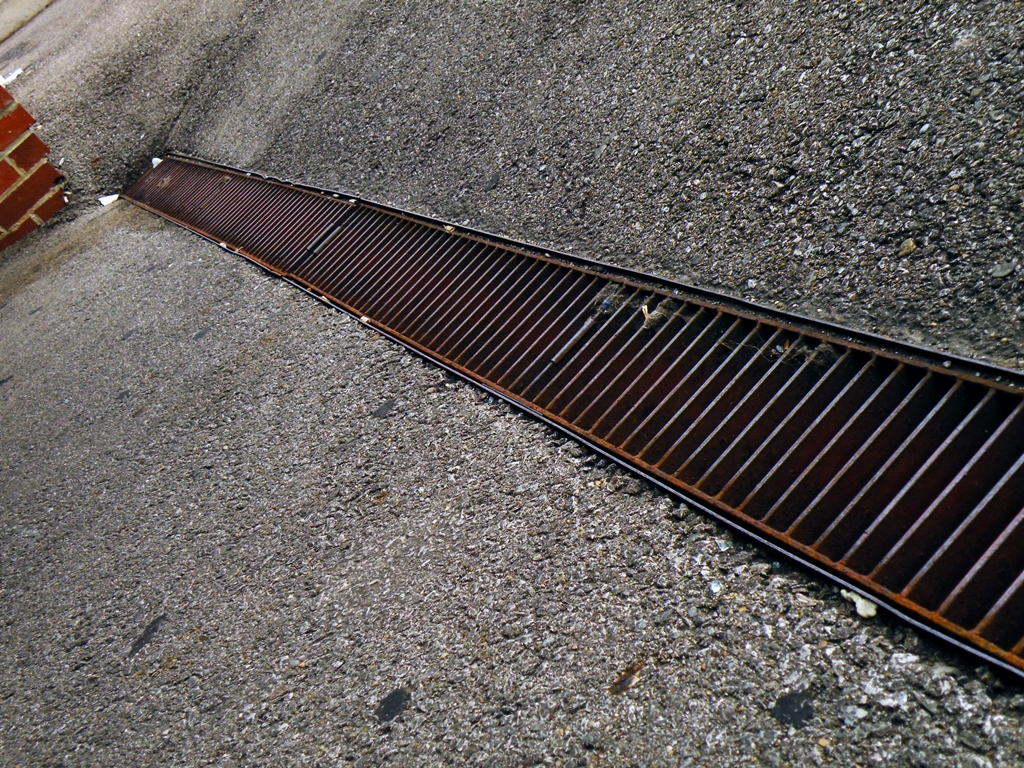
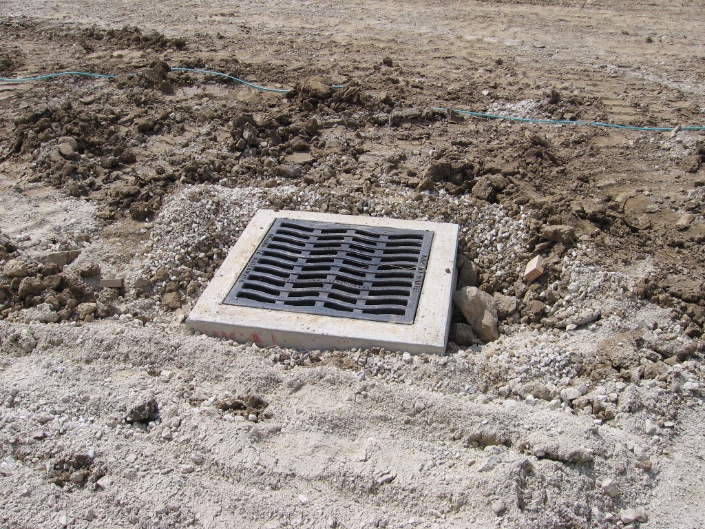
Rainfall on impervious surfaces such as paving and roof structures will result in storm water run-off. Successive site improvements will trigger a requirement for an engineered system to thoughtfully manage storm water run-off. In improved locations such as new suburban subdivisions, the amount of run-off is significantly increased compared to that of the previously undeveloped acreage. Storm water management is achieved through storm drainage utilities, which are comprised of a physical network of site grading, curbs, culverts, catch basins, piping, manholes and, sometimes, retention or detention ponds. Another aspect of storm water management is government regulation, which may impose water quality discharge standards and limits on how much site improvement can be authorized at sensitive project locations.
The first step in the design of a storm water drainage system is to calculate the magnitude and timing of peak flow that a catchment area (or watershed) will generate, since this data will drive the utility design. A topographic survey and an understanding of how planned site improvements will affect the existing site elevations are required to identify the limits of the catchment area (or watershed). The catchment area can be of any shape or size. Its area is defined by analyzing the final site elevations and determining the boundaries at which rainfall water will flow into the catchment area, or off site to an adjacent catchment area. The Continental Divide is a very familiar example of a (quite large) catchment area boundary for flow into the Pacific and Atlantic Oceans. Once the catchment area is defined, the next step is to determine and tabulate the extent of site improvements and natural site features within it.
Although there are many equations, methods, and computer programs available to calculate storm water run-off, the most widespread and basic method used for decades is the rational method. Peak flow is calculated by multiplying the rainfall intensity for a particular storm event, times the catchment area, times the run-off coefficient(s) for the various surface conditions (pavement, woodland, grass) present. The run-off coefficients approach 1.0 for perfectly impervious surfaces, and are less than 0.3 for surfaces such as woodlands that will provide high levels of rainfall infiltration. Weighted averages to represent varied conditions across the site can be performed. Peak flow is assumed to occur at the catchment area’s “time of concentration”, or the first instant when all locations within the catchment area are contributing flow into the drainage system. Rainfall intensity is assumed to be consistent throughout the storm event.
All flow calculation methods address the basic parameters of catchment area, rainfall intensity, storm recurrence, and site features, with varied degrees of applicability and accuracy for particular sites. Conveniently, one acre-inch of rain per hour is nearly equivalent to one cubic foot per second (cfs) of flow. Peak flows and pipe capacities are both defined in cubic feet per second. Pipe sizing is straightforward once peak flow is known. Then the remaining system components, including inlets and manholes, can be matched to ensure that their intake capabilities are compatible with the expected peak flows and pipe sizes. The various components of a storm water utility are addressed in the 33.44 series of the CSI Master Format.

Buildipedia Staff
The Buildipedia research and writing staff consists of dozens of experienced professionals from many sectors of the industry, including architects, designers, contractors, and engineers.
Website: buildipedia.com/