Case Study: Water Supply Infrastructure
-
font size
decrease font size
 increase font size
Located in Freeport, Pennsylvania, about a 30 minute drive north of Pittsburgh, Buffalo Township’s water treatment plant produces over 700,000 gallons of fresh water daily. The plant provides drinking water to over 5,000 residents in Buffalo Township and Freeport Borough. It is also the fresh water supplier for the Municipal Authority of South Buffalo Township. Join Buildipedia for a photo tour of Buffalo Township’s water treatment plant, as we trace the flow of water from the Allegheny River to its distribution throughout the utility.
Buffalo Township’s water treatment plant has been in use since the early 20th century, and its exact site has supported water treatment operations dating to before the Civil War. It’s a well seasoned plant with a long site history, and it remains an excellent example of the water treatment technologies that are utilized every day around the world, particularly in smaller municipalities.
Buffalo Township's Water Supply Infrastructure
Water is drawn from the Allegheny River and chemically treated to remove dissolved solids, to improve taste and remove odor, and also to facilitate the ensuing sedimentation and filtration process. The chemical additives are mixed and agitated, then given time to coagulate and settle in sedimentation basins.
Leaving the sedimentation basins, the treated water is filtered and chlorinated and stored in a clear well beneath the floor of the treatment plant. Water quality is routinely tested and analyzed before it is pumped throughout the potable water utility system from the clear well. A network of pumps, water storage tanks, pumping stations, and underground piping efficiently distributes the water to the homes and businesses in Buffalo Township’s service area.
Don Amadee, Manager, Municipal Authority of Buffalo Township, Pennsylvania, was a technical contributor to this feature.


Head House and Wet Well
The Head House is the starting point of Buffalo Township’s water treatment process. Just outside the two windows shown is the Allegheny River. River water is pumped up from a wet well, which is connected to the river, 36’ -0" below. An intake pipe at the bottom of this wet well extends 60’-0" out into the river.
Chemical Additives
As water is drawn from the wet well, the following chemicals are added in the Head House:
- Powdered Activated Charcoal (PAC): Controls odor and taste
- Potassium Permanganate (KMnO4): Oxidizes dissolved solids
- Polyaluminum Chloride: Aids in flocculation
Potassium Permanganate
A strong oxidizer, KMnO4 appears pink in solution. It will combine with dissolved manganese (Mn) in the river water to form manganese dioxide. It will also combine with dissolved iron (Fe) in the river water to form iron oxide. Both of these chemical compounds can then be readily removed by the filtration process. Without treating the water with an oxidizer like potassium permanganate, manganese and iron (and other dissolved solids) in drinking water would remain in solution, staining plumbing fixtures and creating maintenance problems.
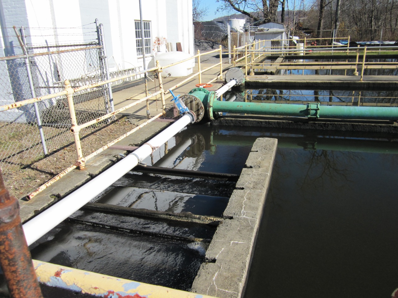
Sedimentation Basins
Two of the four sedimentation basins for the plant are shown. The sedimentation basins are 72'-0" long, 14'-0" wide, and 14'-0" deep. An agitation basin is located in the far corner of this pair of sedimentation basins. River water containing PAC and KMnO4 is piped into the agitation basin from the Head House through the green metal and white PVC piping shown.
Agitation Basin
Chemically treated water entering the agitation basin is forced through a series of baffles. One baffle touches the floor of the sedimentation basin but not quite extend to the water surface. The other baffle will do the opposite -- extend to the water surface but provide a flow gap at the basin floor. The net effect is good mixing of the chemical additives as the treated water flows up and down through these baffles, which aids in “flocculation" -- the formation of large and filterable chemical precipitates in the water.
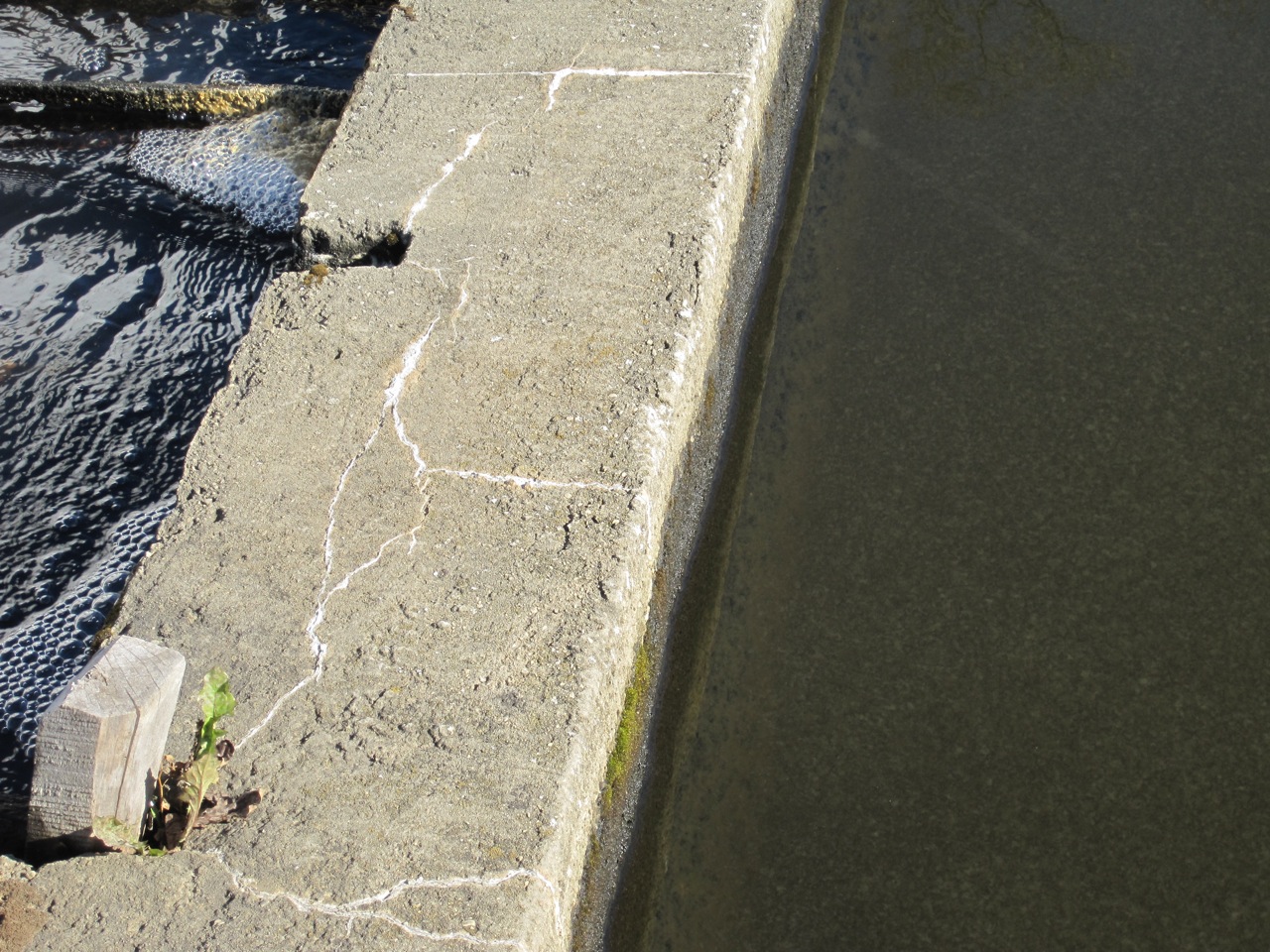
Concrete Wall Between Agitation and Sedimentation Basins
Note that in the agitation basin on the left side of the concrete wall, the water is disturbed as it moves through the vertical baffles. To the left of the wall, the “flocs” (chemical precipitates generated by the chemical additives) have already formed and are visible in the sedimentation basin.
Flocs
Flocs forming in the sedimentation basins. A thin wire cable stretched across a basin provides a size perspective.
Flocs
A close-up of flocs suspended in the chemically treated water in a sedimentation basin at the treatment plant.
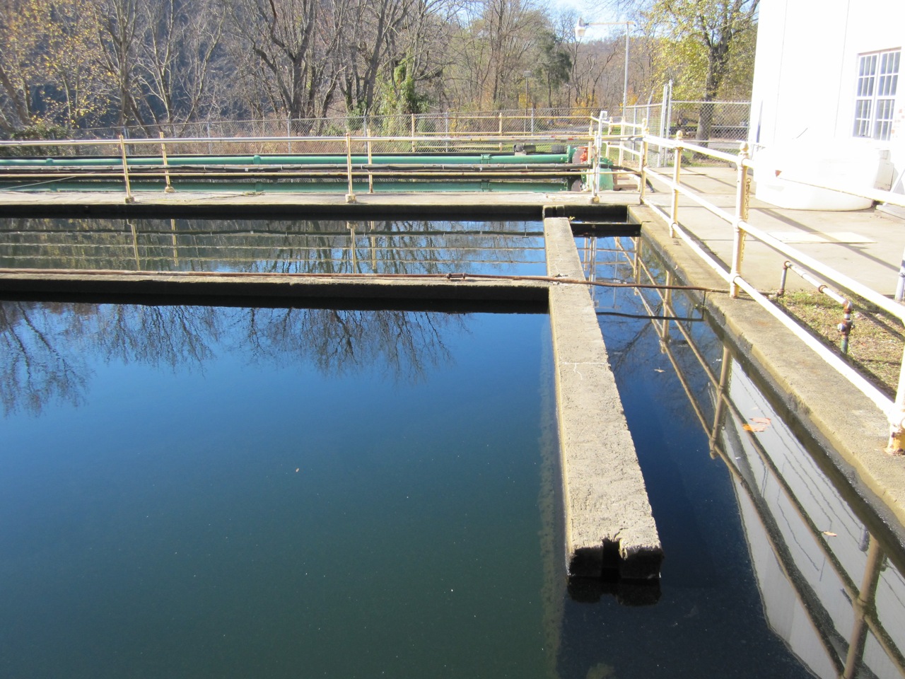
Sedimentation Basins
A view across the back end of all four sedimentation basins. The furthest sedimentation basin contains the agitation basin. Water flows length-wise through the sedimentation basins, alternating its flow direction between adjacent basins. This length-wise circuit through the sedimentation basins provides the necessary time for flocculation and sedimentation to occur. Two of the four sedimentation basins can be taken off-line for maintenance if needed. After the sedimentation basins, the treated water flows into the filter room. There are two filter chambers in the white brick building located to the right.
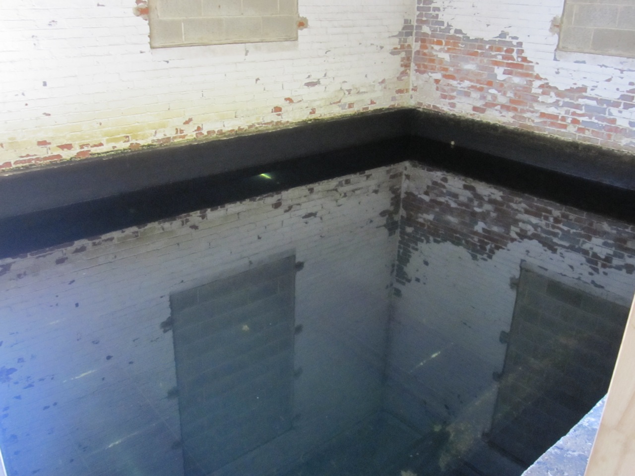
Filter Room
Water enters the filter room from the sedimentation basins. At the bottom of this filter chamber is a stratified array of granular filter materials, held in place by simple gravimetrics. The uppermost material in the filter is anthracite charcoal, then silica sand, and finally gravel of various sizes (up to size #3 or #4 stone at the very bottom). The walls of the filter room are reflected by the water surface.
Filter Jar
The filter materials contained in this jar are representative of the various filter media mentioned above.
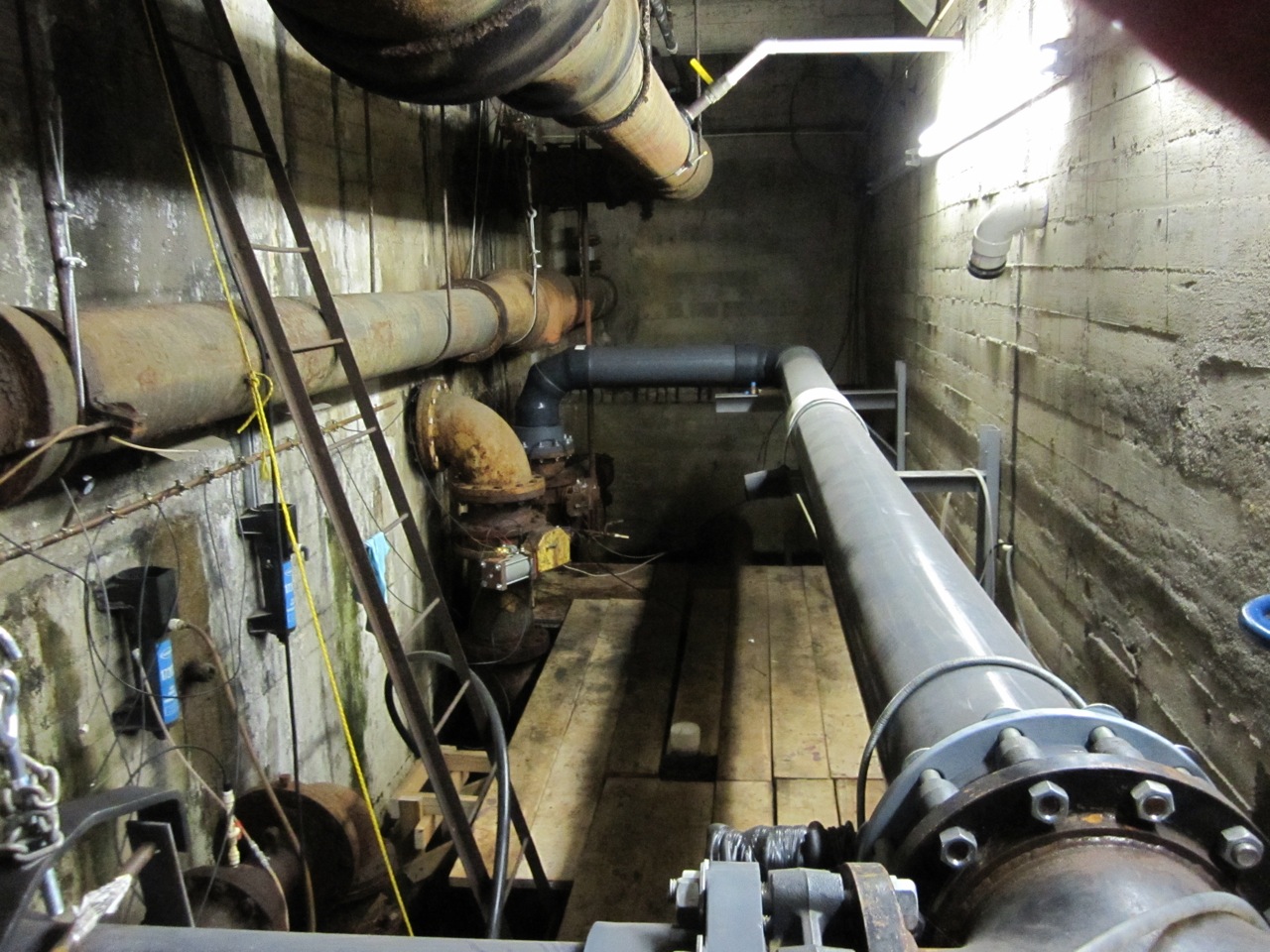
Under-drain System Piping
Piping located beneath the filter room will transfer the filtered water into the clear well. Note the elbow fitting to the left in the background.
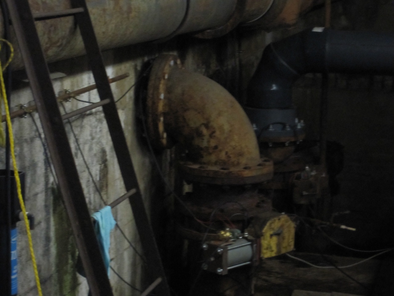
Filter Room Under-drain Pipe
This elbow fitting and pipe is where water is drawn from the bottom of one filter and then transferred to the clear well.
Under-drain System Piping
This under-drain system alongside the plant’s filters dates back to 1919.
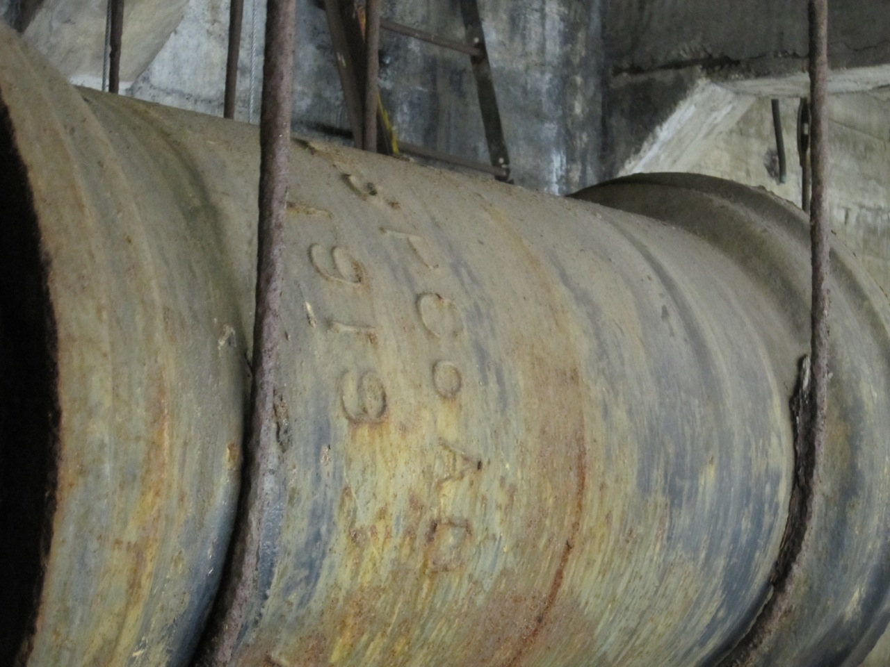
1919 Date Stamp
Date-stamped pipe manufactured in 1919.
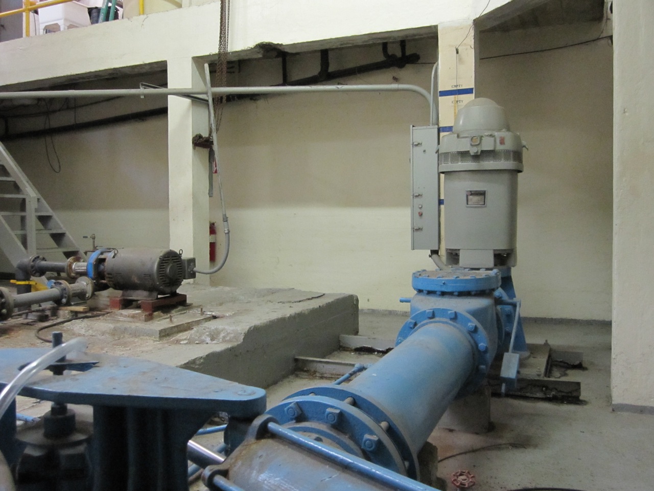
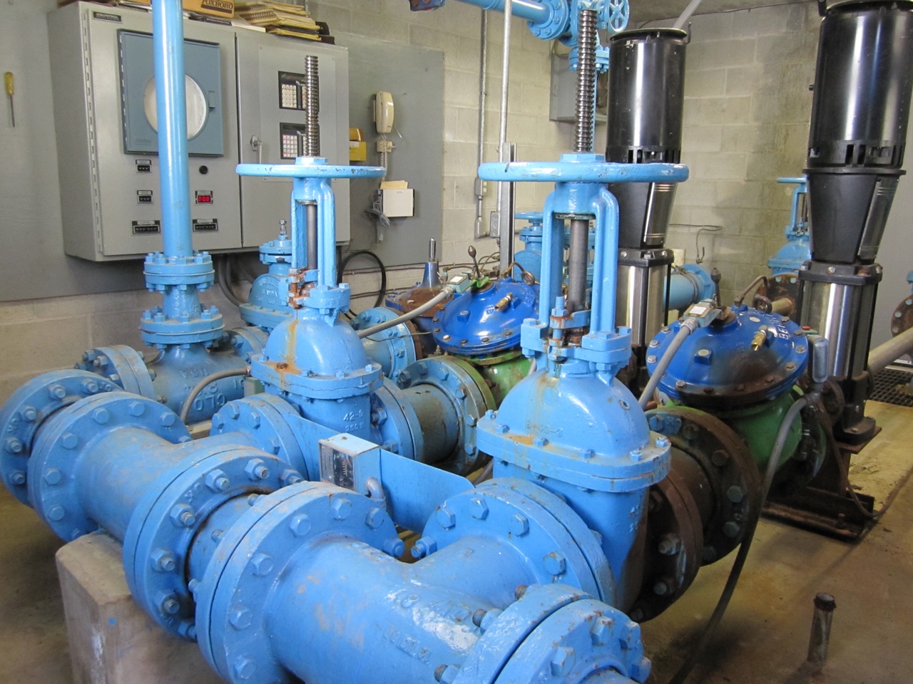
Pump Room
Water leaving the filtration process is stored in a clear well beneath the pump room at the treatment plant. These pumps are used to pump processed potable water from the clear well into the community throughout the distribution system. The pumps are also used to reverse the flow of water, and can draw water from the clear well to backwash the filters. Filter backwashing is typically done every 2-3 days.
Water Distribution Pump
One of the pump room distribution pumps.
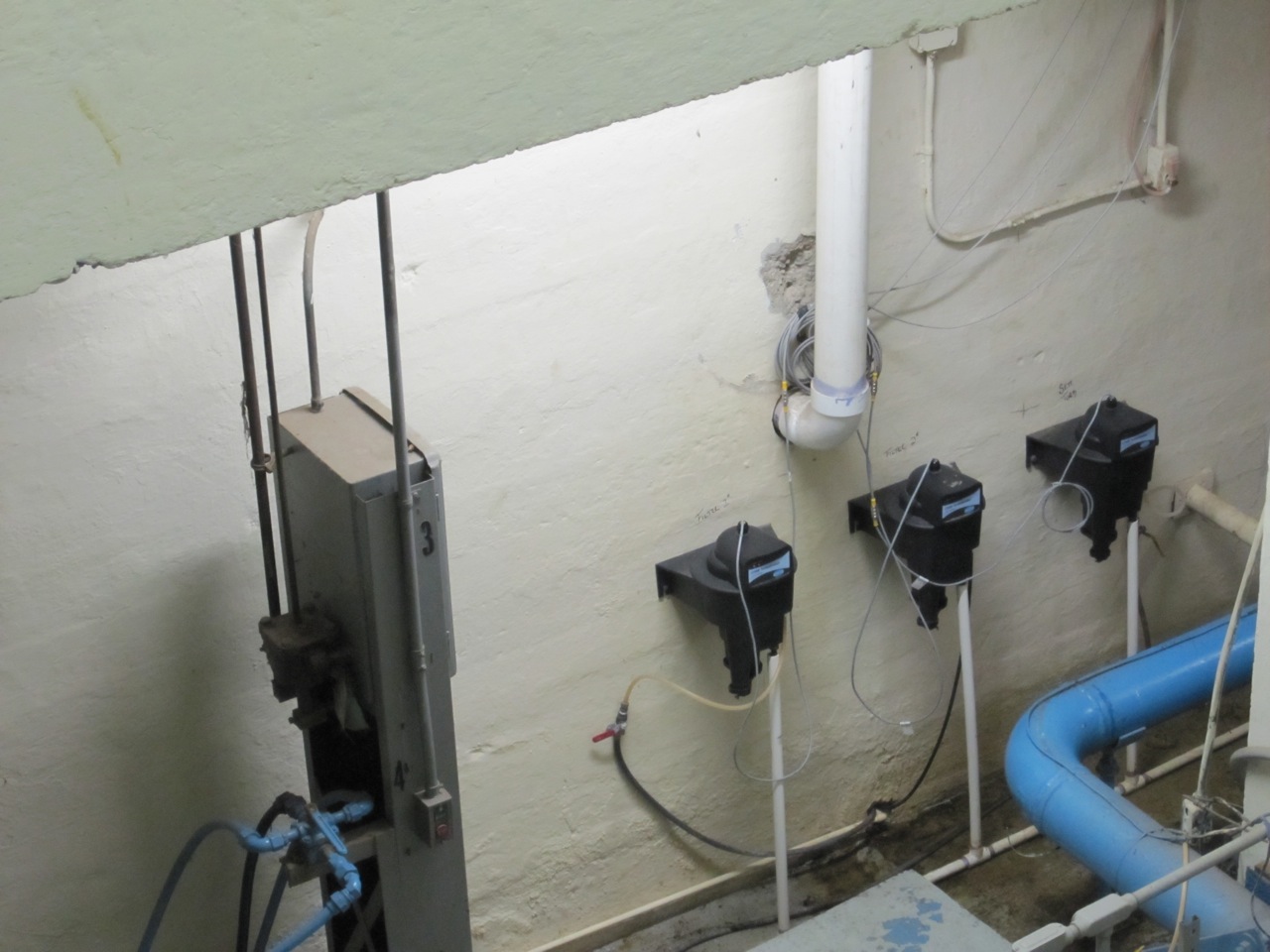
Pump Room
The under-drain piping system for the filters is directly behind the wall of the pump room. Note the three turbidity meters installed on the wall.
Turbidity Meters
Turbidity meters measure the amount of suspended solids (fine debris) in the water by evaluating the ability of a beam of light to pass through a water sample. These are in-line turbidity meters that continually measure and record turbidity. It’s interesting that the plant operators can predict and witness slight turbidity changes based on the local weather, and even if a tug or barge passes by the Head House on the Allegheny River.
Turbidity Recorders
At the plant operator’s station, turbidity measures are continually monitored and recorded.
Chlorine Disinfection System
Chlorination of treated water supplies is necessary to kill bacteria in the water. Chlorine is a strong oxidizer and disrupts the chemical functions in the bacteria's cells that are required for them to live. Chlorine in treated water is depleted as it kills bacteria, so an important element of proper chlorine dosing at the treatment plant is the creation of “free available residual chlorine” in the water supply. Drinking water stored in pipes and tanks throughout the overall system must still contain enough available residual chlorine to kill bacteria long after the initial water treatment at the plant.
Metering of Chlorine Gas
Chlorine gas placed in water will form hypochlorous acid, hydrogen ions, and chlorine ions. Hypochlorous acid is the main disinfectant. The levels of “free available residual chlorine” that can be expected throughout the system are influenced by the presence of other chemical compounds in the water (including agents specifically added to manage chlorine chemical reactions).
Lab Testing Equipment
The plant operator will routinely conduct operational level (not regulatory compliance) checks on the treated water. Hardness, alkalinity, iron, and manganese levels are checked twice daily. pH levels are another important consideration for the treated water. Pipe and pump corrosion can result if the treated water is too acidic. pH levels also will impact the effectiveness of the residual chlorine in the water supply throughout the distribution system.
Pump Controllers and Recording Gauges
Operation of the water treatment plant’s distribution pumps is automatically controlled based on water volumes and pressures sensed throughout the entire storage and distribution network.
Recording Gauges
Each potable water storage tank in the system has its own water level recording gauge that can be monitored at the treatment plant.
An Individual Water Tank Recording Gauge
In this photo, the Sunset Tank shows a water level of 75'-3" on the digital display. The recorder below provides a graphical history of recent water levels in this tank.
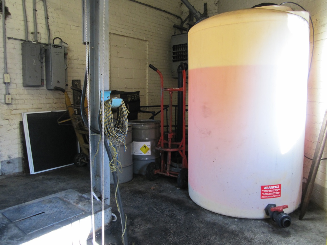
Caustic Soda
The pH level of the treated water entering the system of storage tanks and piping is important not only for residual chlorine calculations. Caustic soda, a base, will increase the water’s alkalinity (ability to neutralize acids) and is dosed into the treated water leaving the plant as needed. Distribution piping will naturally form a thin interior lining of protective calcium that precipitates out of drinking water. Acidic drinking water will dissolve this coating, resulting in higher rates of pipe deterioration and maintenance costs.
Freeport Water Storage Tank
A view of Freeport, Pennsylvania. A water storage tank sits on the ridgeline above the town.
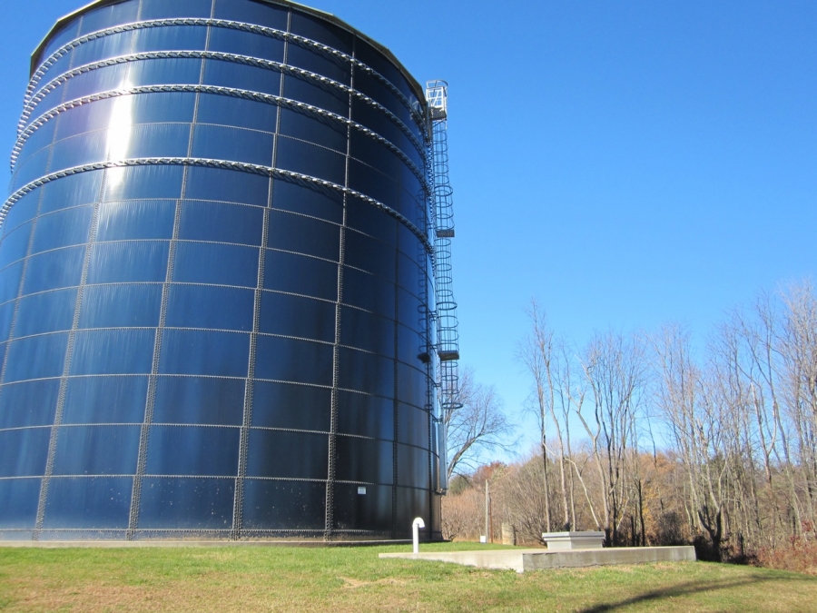
Bolted Steel Water Storage Tank
Bolted steel tanks have exceptional durability and capacity.
Water Tank Plate
A small sample of a ceramic coated steel plate used in water storage tank construction.
Water Storage Tank and Valve Pit
Another view of the bolted steel water storage tank. Note the valve pit constructed in the ground to the right of the tank.
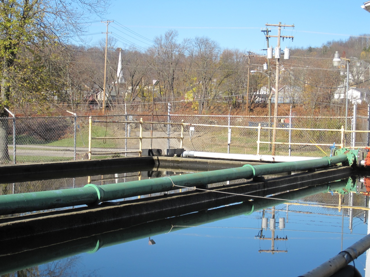
In the Valve Pit
This manifold piping contains an altitude valve and a check valve. This pipe and valve arrangement ensures that the tank above is filled to the 60’-0" level, but then drawn down to the 45’-0" level during system use, before any new water is added. This ensures good mixing of the water stored in the tank, so no stratified layers of depleted residual chlorine can form in the stored water column. Zones of depleted residual chlorine in the tank would allow for the growth of pathogens in the water supply.
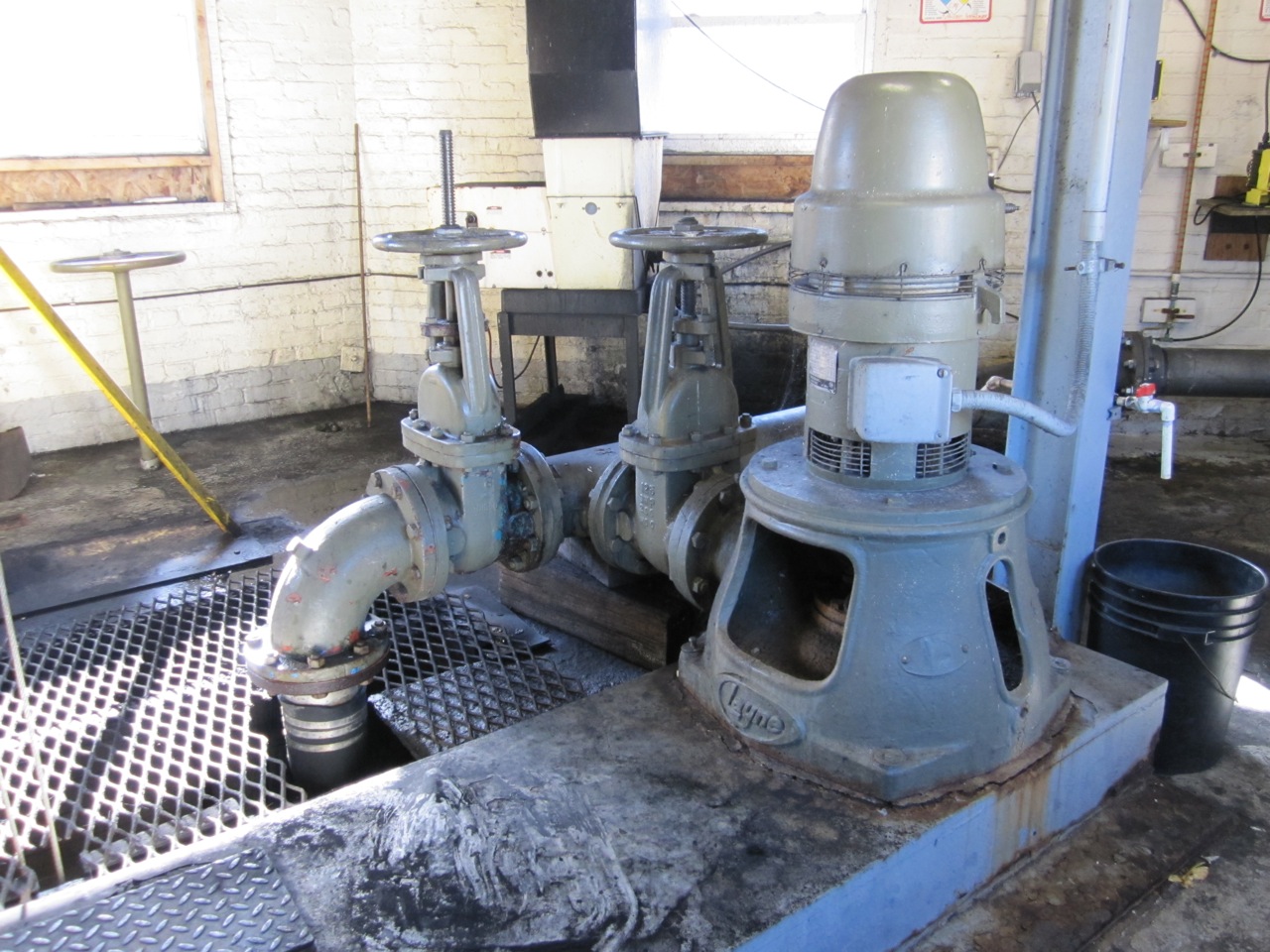
In a Pumping Station
New turbine pumps and piping in a water pumping station alongside Buffalo Creek. Water in the piping system leaves here at 250 psi. Head losses and pressure-reducing valves throughout the water distribution network are taken into account so most homes will receive their water at about 60 psi.
Water Tanks
Two water tanks near Sarver, Pennsylvania. A typical standard for municipal water systems of this size is to store enough potable water to supply the community for five days without processing any new water.
Water Tank
A water tank placed at the highest point in the water distribution system. This site location offers several advantages. It helps to pressurize the piping network without the use of pumps, saving on electricity costs. In the event of a sustained power failure, drinking water still can be distributed because of the static head created by this and other carefully placed water storage tanks throughout the system.
The New: Welded PVC Piping
Many modern water utilities are trending toward welded PVC pipe for their water distribution piping. PVC is a flexible, durable, and lightweight choice, and it can now be welded together. A manufacturer’s sample of welded PVC piping is shown here. Most water utilities like the Municipal Authority of Buffalo Township rely heavily on PVC piping throughout their water distribution networks.
The Old: Pre-Civil War Wooden Piping
A photo worthy of general interest. A section of pre-1860s wooden water pipe removed from beneath the streets of Freeport, Pennsylvania during an excavation. Note the carefully milled pipe joint.


Andrew Kimos
Andrew Kimos completed the civil engineering programs at the U.S. Coast Guard Academy (B.S. 1987) and the University of Illinois (M.S. 1992) and is a registered Professional Engineer in the state of Wisconsin. He served as a design engineer, construction project manager, facilities engineer, and executive leader in the Coast Guard for over 20 years. He worked as a regional airline pilot in the western U.S. before joining the Buildipedia.com team as Operations Channel Producer.
Website: buildipedia.com/channels/operations