Case Study: Water Quality Retrofit and Retaining Wall Remediation
-
font size
decrease font size
 increase font size
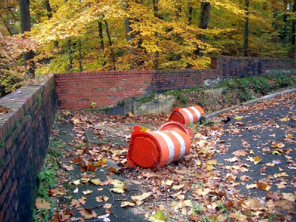
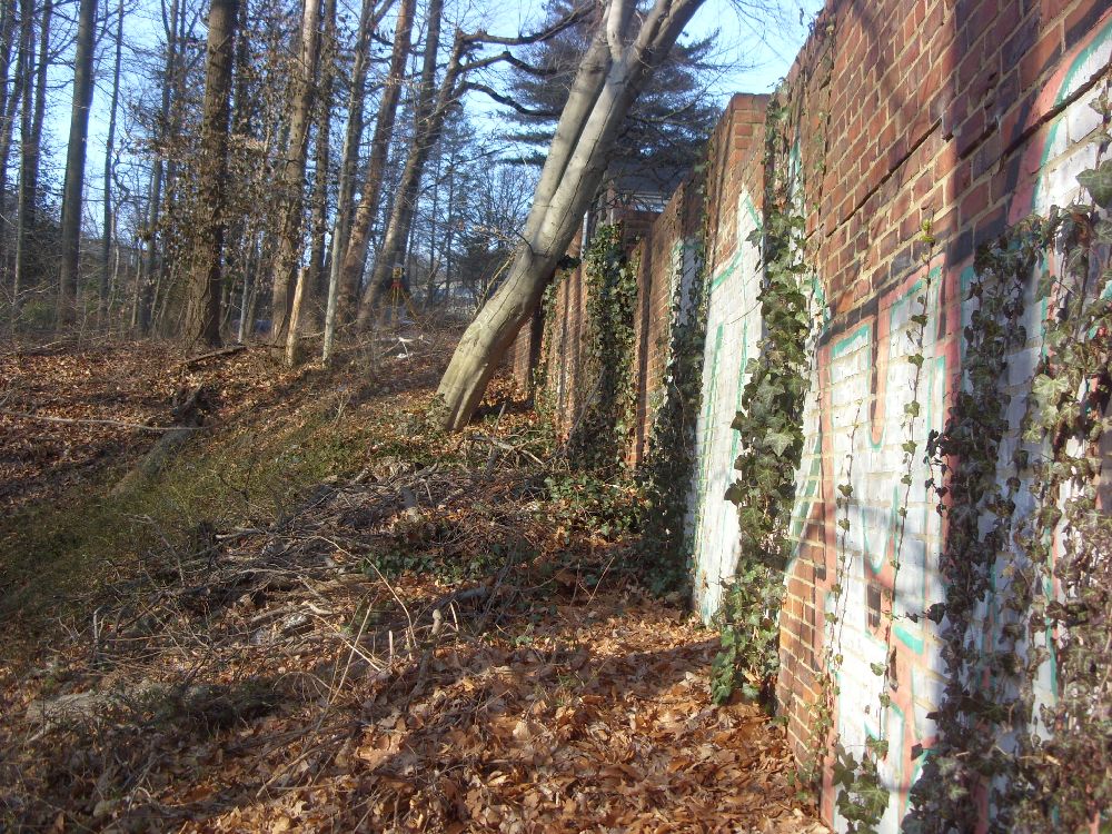
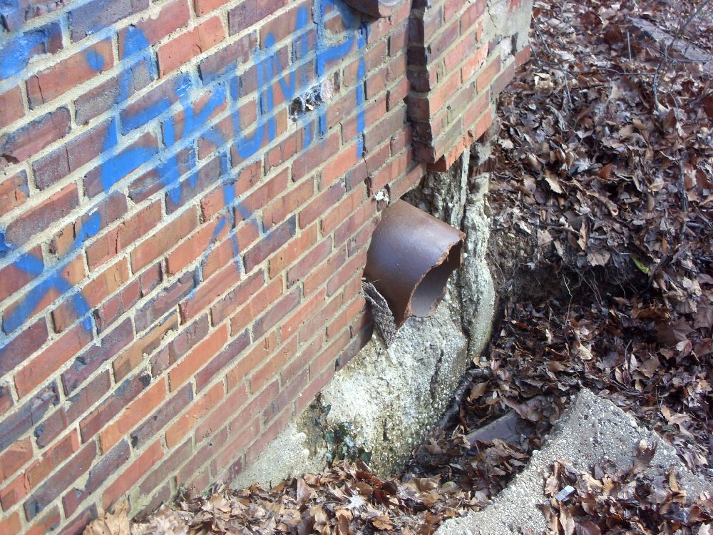
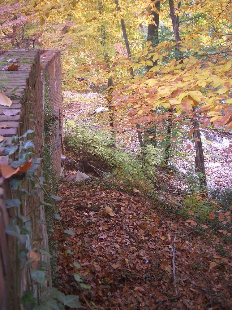
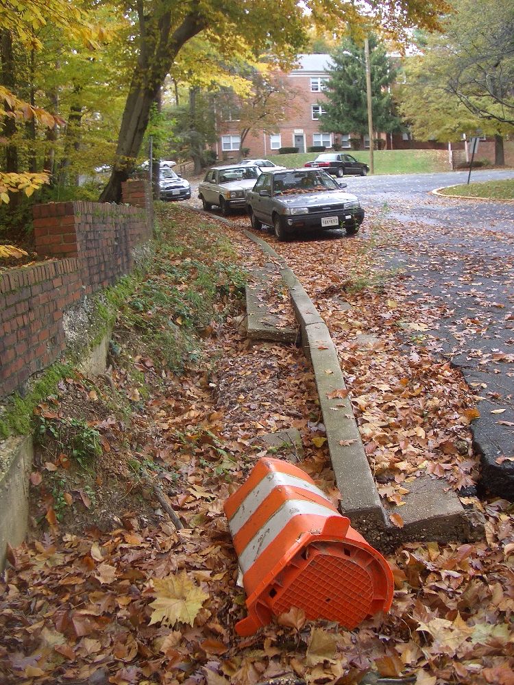
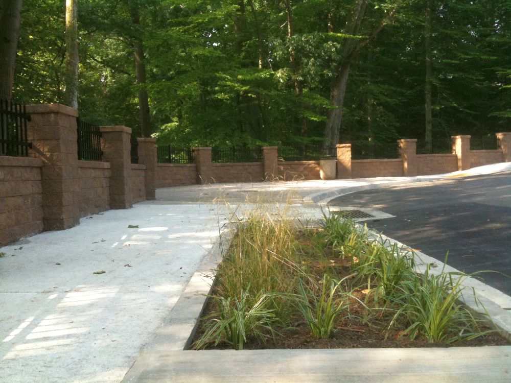
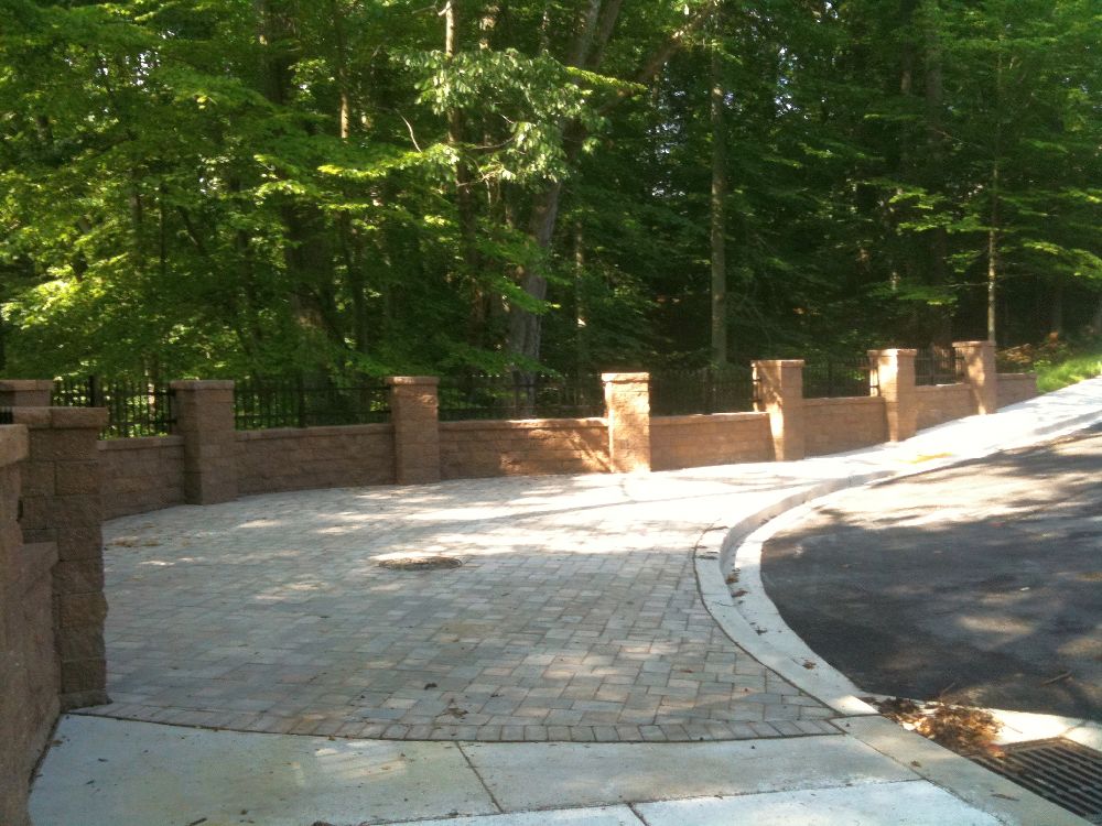
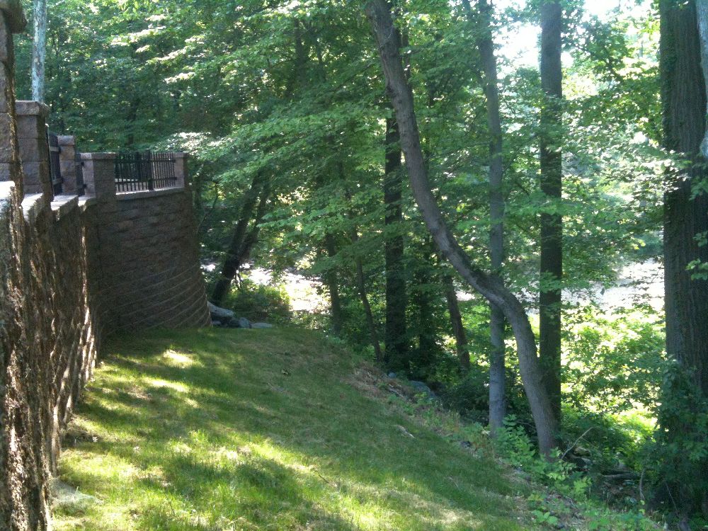
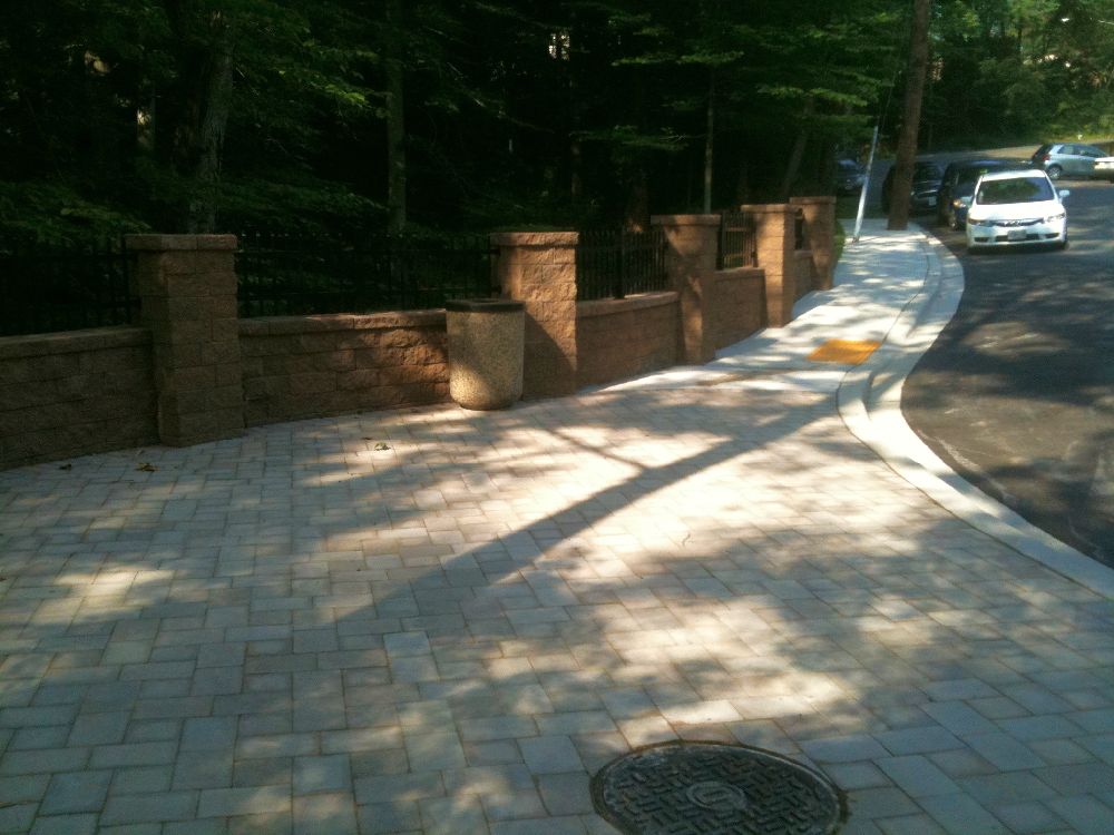
The City of Takoma Park, Maryland, needed to replace a failing retaining wall that supports a roadway in a small residential development. The Linden Avenue site is directly adjacent to Sligo Creek, which is a tributary of Anacostia Creek, a river undergoing a significant restoration effort. T. E. Scott & Associates, Inc., designed a replacement for the failing retaining wall infrastructure, created a pocket park for the local residents, and provided water quality treatment for the unmanaged watershed. This combination of aesthetic and environmental improvements adds value to the project. We�ll look at some stormwater flow design calculations, a storm water flow splitter, an urban modular wetland unit, a step/plunge pool, and an interesting retaining wall design.
 Credit: T. E. Scott & Associates
Stormwater
Stormwater Flow Design Calculations
The Stormwater Management Drainage Area Map (Sheet #11) is more important than its position as the last drawing in the package shown at right might indicate. Its calculations shaped this design and determined the required construction elevations. A topographic analysis determined the catchment area necessary to produce stormwater run-off for this project. Any stormwater run-off within the catchment area (delineated by dashes on Sheet #11) needed to be managed by the design. Projected rainfall outside the catchment area would not impact the project�s stormwater flow calculations. The project�s catchment area [or drainage area (DA)] was found to be 1.6 acres (as shown on Sheet #11).
The Rational Method (Q = CiA) was used to determine the 10-year storm water flow for this 1.6-acre catchment area. The Rational Method has been around for 100 years or so, and it�s still a great tool for an application like this.
Q = peak storm water flow in cubic feet per second (cfs).
C = the run-off coefficient, or the proportion of rainfall that actually creates stormwater run-off across a particular catchment surface. Higher numbers indicate a more impervious surface, with 1.0 being the absolute maximum. C = 0.7 in this case.
i = intensity of rainfall in inches per hour. i will vary with storm event frequency.
A = the catchment area in acres.
Since 1 cfs equals almost exactly 1 acre-inch per hour, the dimensions of these variables balance to conveniently allow for peak flow, Q, in cfs.
Tc = time of concentration, or the time it takes for all portions of this 1.6-acre catchment area to contribute to peak flow, Q, at the low point (the single curb inlet in this design). Tc was determined to be 5 minutes. When the Rational Method is used, it assumes that rainfall intensity, i, will occur consistently during the catchment area�s time of concentration, Tc.
The conclusion of these calculations was that there would be a peak flow, Q, of 8 cfs created by a 10-year storm event at this location. Specifically, a rain fall event of 7.07 inches per hour, for five minutes throughout 1.6 acres at this project site would produce 8 cfs of stormwater flow. (This is also referred to as Q10 on Sheet #11.) This design could proceed once Q10 was calculated.
Flow Splitter
Stormwater flows produced by storm events of 1� or less enter the single curb inlet and are routed through a 15� reinforced concrete pipe (and/or the 4� low-flow orifice pipe contained within it) to a modular urban wetland.
Any stormwater flows that exceed the 1� rainfall depth are split off and routed directly to the 18� main reinforced concrete pipe (RCP) discharge line. Commonly referred to as an �off-line� facility, the flow splitter prevents pollutants trapped in the modular wetland from being resuspended during a large storm event and conveyed downstream.
The �Flow Splitter Details� drawing in the Stormwater Management Profile and Details (shown on Sheet #9) provides a good illustration of this concept and is a good visual aid for the discussion. The equations that appear on Sheet #11 show how the elevations required for the flow splitter to function properly were calculated.
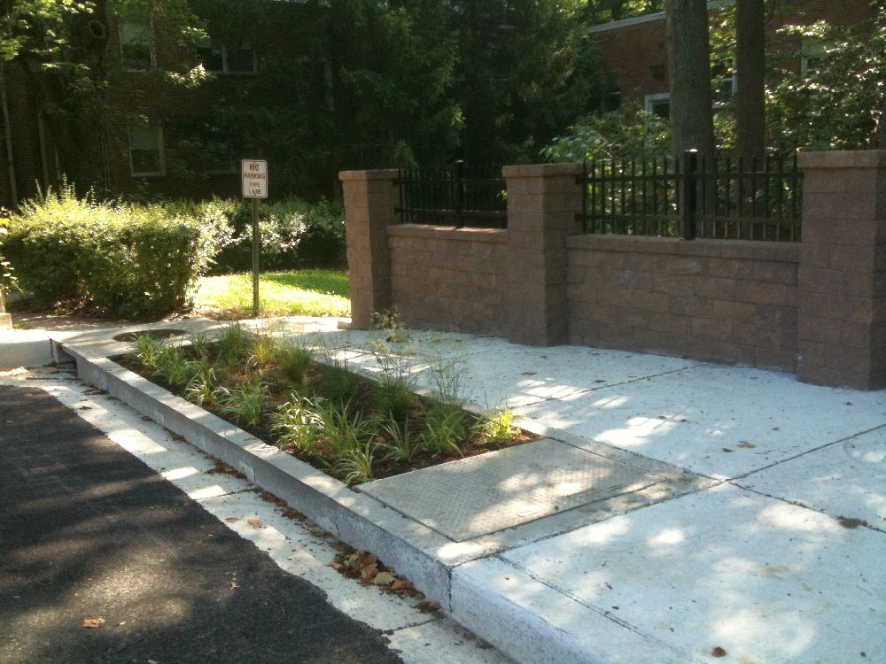
Modular Urban Wetland Unit
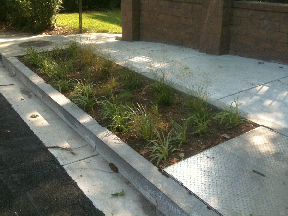
The flow splitter protects the integrity of a modular urban wetland unit downstream of this project�s single curb inlet. The great majority of rain storm events (approximately 90%) result in less than 1" of rainfall run-off, producing routine and manageable flow rates that are readily treated before their discharge into the environment. This stormwater treatment occurs in the modular urban wetland unit. The wetland unit, although it contains its own integrated high-flow bypass piping, is not intended to accommodate massive stormwater flows from the curb inlet. The plantings, soil, and gravel within the wetland unit would be damaged by high flow rates if that were to happen.


Modular Wetland Details (Sheet #10) shows plan and elevation views of the modular urban wetland unit used in this project. This particular wetland unit is a linear curb type, manufactured by Modular Wetlands of Oceanside, California. The modular wetland unit treats the stormwater flows through a combination of capture, screening, sedimentation, filtration, bioretention, and flow control.
Discharges from the urban wetland unit and high flows (those in excess of 8 cfs, short-circuited by the flow splitter) are field-connected along the main 18� RCP run. Stormwater enters the project�s single manhole during this main pipe run. Downstream of the manhole, stormwater spills through a new step/plunge pool as soon as it is transported through the new retaining wall.
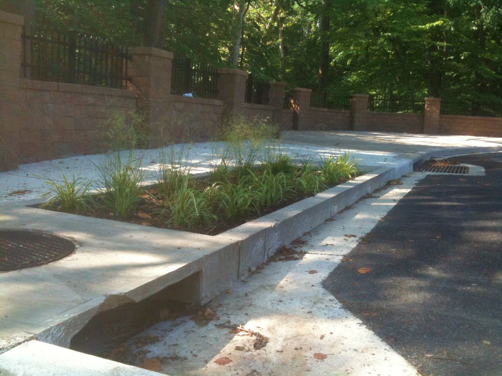
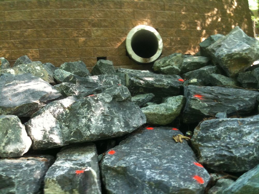
Step/Plunge Pool
The step/plunge pool provides at least three distinct functions. First, it dissipates the hydraulic energy from the stormwater flow from the main outfall, which may reach a significant level. Second, it works as a stormwater quality management device because it provides an opportunity for settlement to occur. This is particularly important considering that any significant flows that bypass the urban wetland would not otherwise receive any quality control. Third, the plunge pool portion of the device allows an opportunity for some shallow groundwater recharge. The rip-rap feature downstream of the plunge pool provides protection against soil erosion and then bank erosion as the stormwater flow finally enters Montgomery County�s Sligo Creek. The YouTube video to the right makes it even easier to see the relative positions of these different features at the finished project site.
Stormwater Flow Profile
The Stormwater Management Profile and Drawings (shown on Sheet #9) show the standard format used for stormwater center-line profiles. The purpose of these drawings is to show the proper construction elevations required for all the stormwater flow management devices and piping discussed above.
You may at first think that this profile represents water flowing from page left to page right, in a consistent direction, but it defines the field elevations required for the project, not the directions that stormwater actually flows in the field. It�s interesting to note that stormwater flows to the northwest from the curb inlet to the modular urban wetland but that it flows in the exact opposite direction, to the southeast, when leaving the urban wetland unit. (A review of the plan view drawings is required to reach these conclusions about the direction of water flow.)
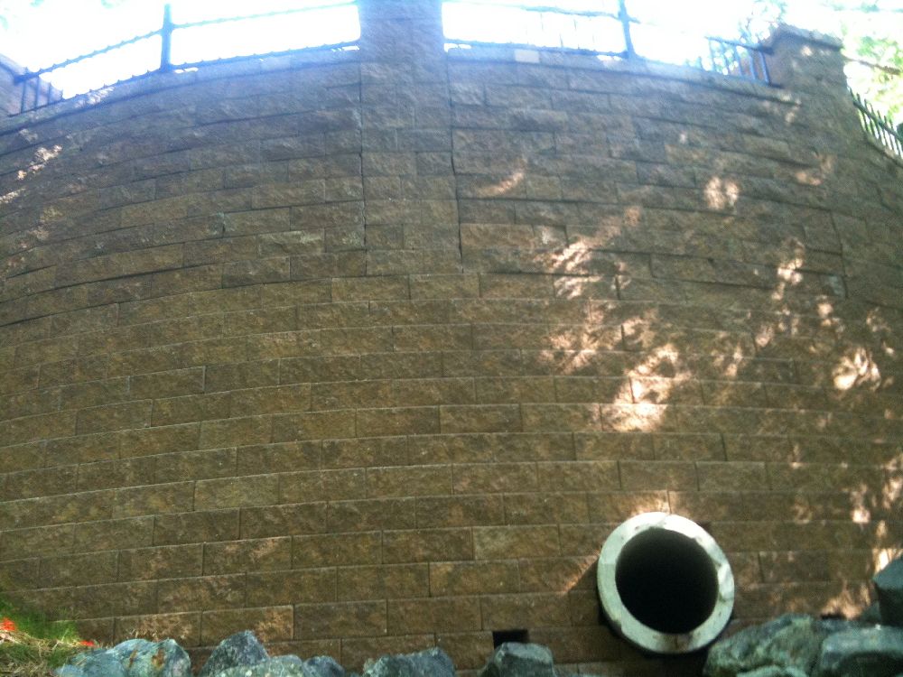
Retaining Wall
Retaining Wall and Geosynthetic Reinforcement
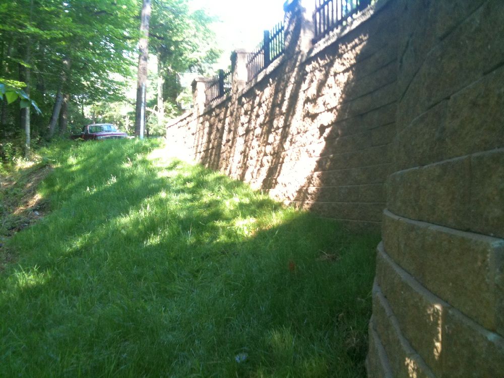
This retaining wall design uses a system of interlocked masonry units [Segmented Retaining Wall (SRW) units] as shown by Retaining Wall Details (Sheet #6). The SRW units are pinned together as they are placed. The specifications in this project refer to the Versa-Lok system, a proprietary retaining wall system.
The tie-back system for this retaining wall is a horizontal array of geosynthetic (high-strength polymer) reinforcement grids attached perpendicularly to the SRW sections. Versa-Grid was the geosynthetic grid specified on this project. Because they were attached to the SRW units where required, the reinforcement grids were rolled out on prepared grade at specified elevations across set site areas. The elevations given in Retaining Wall Details (Sheet #6) show these geosynthetic reinforcement grids as thin horizontal lines.

The drawing notes emphasize the importance of the proper placement of the geosynthetic reinforcement. For example, no tracked equipment can pass over the reinforcement grids unless 6" of backfill have already been placed upon them. Rubber-tired equipment can travel across uncovered reinforcement grids at speeds not to exceed 5 mph. The high-strength direction of the grid matrix must be perpendicular to the wall, and it must be connected to the wall in a particular fashion at a specified tension before backfilling.
There�s good reason for these notes. The integrity of the reinforcement grids is important because the backfilled soil placed upon them provides stability for the retaining wall. Similar designs allow for the use of geosynthetic reinforcement �fabrics� (solid sheets) or these �grids� (open matrix). The retaining wall in this project is 10.5' high in some locations. Five layers of geosynthetic reinforcement grid are fitted to these highest wall sections at the specified field elevations as shown in the Retaining Wall Details (Sheet #6).
This compact project site at Linden Avenue in Takoma Park, Maryland, is full of interesting features and concepts that could be applied to larger projects. Project construction was performed by Rustler Construction and completed in June 2010.
Theodore (Ted) E. Scott is the president of T. E. Scott & Associates, Inc., in Hunt Valley, Maryland. He provided construction drawings and notes for his firm�s design project in Takoma Park, Maryland, titled �Linden Ave. Water Quality Retrofit and Retaining Wall Remediation.� Buildipedia.com has reviewed his plans and captured some highlights for our audience.

- Sheet_1___Title_Sheet.pdf (1942 Downloads)
- Sheet_2___Existing_Conditions_and_Demolition_Plan.pdf (1839 Downloads)
- Sheet_3___Site_Grading_and_Utility_Plan.pdf (2009 Downloads)
- Sheet_4___Site_Details.pdf (2097 Downloads)
- Sheet_5___Retaining_Wall_Profile_and_Details.pdf (1894 Downloads)
- Sheet_6___Retaining_Wall_Details.pdf (2165 Downloads)
- Sheet_7___Erosion_and_Sediment_Control_Plan.pdf (1944 Downloads)
- Sheet_8___Erosion_and_Sediment_Control_Details.pdf (1807 Downloads)
- Sheet_9___Stormwater_Management_Profile_and_Details.pdf (2187 Downloads)
- Sheet_10___Modular_Wetland_Details.pdf (2378 Downloads)
- Sheet_11___Stormwater_Management_Drainage_Area_Map.pdf (1801 Downloads)

Andrew Kimos
Andrew Kimos completed the civil engineering programs at the U.S. Coast Guard Academy (B.S. 1987) and the University of Illinois (M.S. 1992) and is a registered Professional Engineer in the state of Wisconsin. He served as a design engineer, construction project manager, facilities engineer, and executive leader in the Coast Guard for over 20 years. He worked as a regional airline pilot in the western U.S. before joining the Buildipedia.com team as Operations Channel Producer.
Website: buildipedia.com/channels/operations