IT Infrastructure Case Study: Baldwin-Wallace College Conservatory of Music
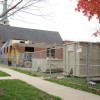
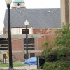
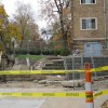
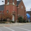
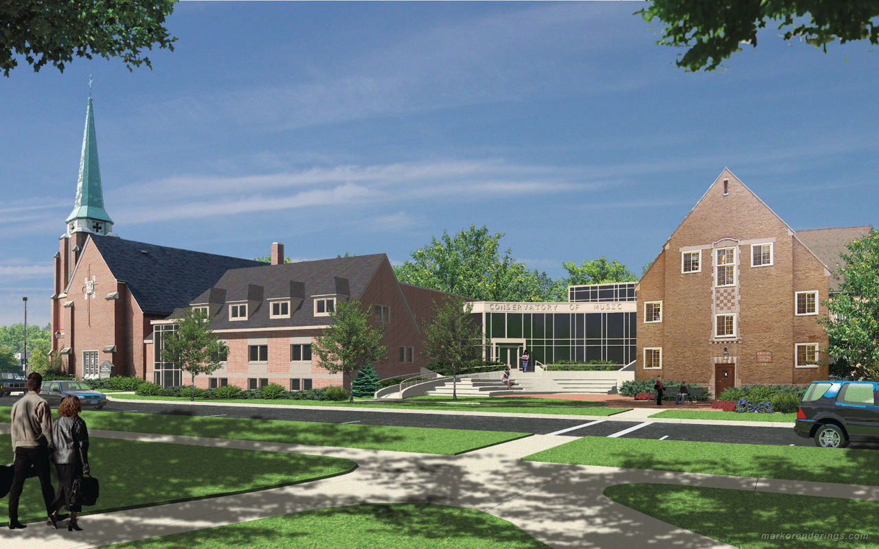
Baldwin-Wallace College in Berea, Ohio, is in the midst of a $20.6 million -- $1.2 million of which represents the information technology (IT) portion -- construction project that will double the physical size of its Conservatory of Music. Expected to be completed by the fall of 2011, the project includes major renovations and new construction; joining two existing campus buildings with the adjacent church complex. Upfront planning is crucial to ensure a good IT installation that meets all the needs of their students and professors and wisely uses capital funds. Here are the basic concepts involved in IT system planning and infrastructure. Greg Flanik and Daniel Stilla from Baldwin-Wallace’s IT department provided Buildipedia a look into the planning and technologies involved in getting their new building “wired for sound.”
Connecting to Existing IT Infrastructure
Whenever a new building or building expansion is proposed, the first planning task is to determine the most efficient route and method to connect to the campus’s existing IT infrastructure. Like most campus environments, most of Baldwin-Wallace’s main campus IT backbone is a buried network of conduits accessible by service manholes. Contained within these conduit runs are copper cables for telephone service, coaxial cable for television, and fiber-optic cables for data (computer) networks and fire alarm systems. An increasingly common option for new telephone service is the Voice over Internet Protocol (VOIP) network. VOIP allows the current data network (wired and wireless) to be used as the conductor for telephone service as well as for data networks, reducing the need for separate copper telephone cabling (minimal copper cable is necessary for emergency services).
If a new building project is conveniently located near established IT infrastructure, an existing manhole can be used as a node for system expansion. If a new campus building is remotely located such that adding a segment of buried conduit/cabling from an existing manhole is not practical, leasing utility pole rights-of-way to string overhead copper and fiber-optic cables is a common alternative. A good example of this approach is Baldwin-Wallace’s IT connection to their Building and Grounds building, which relies upon utility pole conductor runs along Bagley Road in Berea.
Baldwin-Wallace College Conservatory of Music
The IT planning for the Conservatory of Music expansion followed the norm, and a connection point to the existing IT infrastructure was identified as the first step. Most of the Conservatory of Music project site was currently connected to the college’s network infrastructure. Stilla was able to plan the required network expansion from the infrastructure currently in place.
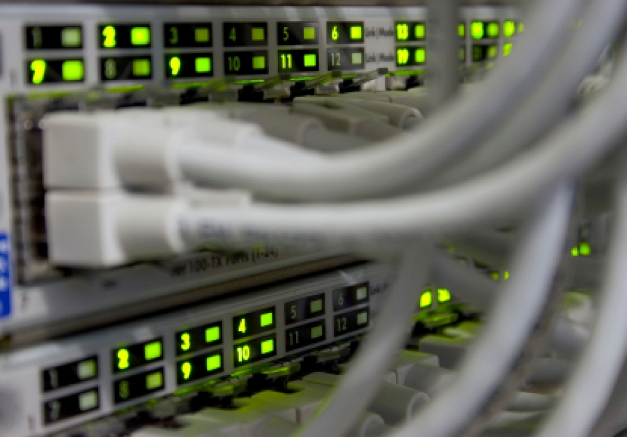
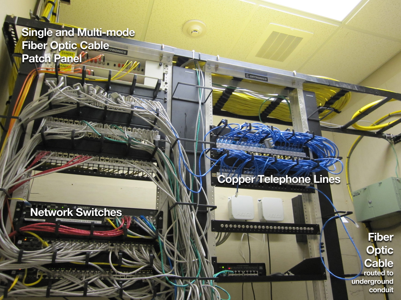
The next step was to identify where network closets within the building complex will be required. Network closets, or “propagation points,” are accessible IT utility rooms within each building space. Network closets contain network switches that connect all the building’s IT devices from every possible end-user location in a building back to the main IT infrastructure. Three network closets are necessary for the new conservatory building, which involves renovating and connecting two existing campus buildings (Kulas Hall and Merner-Pfeiffer Hall) to a renovated church (formerly the First Congregational United Church of Christ in Berea). Two of the three required network closets were already located in Kulas Hall and Merner-Pfeiffer Hall. The third network closet needed to be placed in the former church building, which represented some challenges due to its massive stone walls.
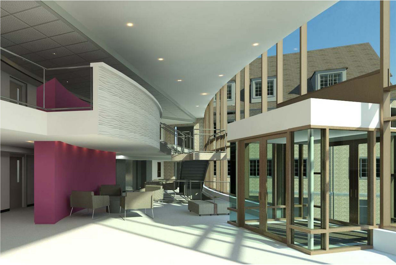
For several reasons, it’s very important for the IT specialists to be involved in new floor plan development from the very beginning. If they are not involved, expensive or visually unappealing IT system retrofits (i.e., conduit runs attached to outside walls) could be necessary. Stilla describes several of the components required when planning network closets for a building.
First, the interior Ethernet cabling, which connects all of a building’s IT devices to a network closet, should not be run in distances that exceed 300’-0". Distances greater than 300’-0" will reduce the performance characteristics of the Ethernet cabling and play an integral part in where the network closet will be located.
Second, water piping should not be located within, or run through, the network closet spaces in a building. There’s risk of damage to expensive IT components if a pipe leak should occur. An option is to reroute water pipes away from a building’s preferred network closet location, but this adds to a project’s cost. Other building systems placed too close to a network closet (i.e., HVAC) tend to create radio-frequency (RF) interference that impacts the function of various IT components.
Third, partnering with an architectural--engineering firm (Weber Murphy Fox for this project) should ensure that network closet locations, conduits, conductors, and IT devices are accurately specified in the final construction documents.
Tracing Back to the Server Room
The goal of good IT planning is to ensure that all the envisioned IT devices within a new building can be efficiently connected to the campus network infrastructure, using existing IT infrastructure to the maximum possible extent. The sequence of basic hardware to consider is:
- A computer jack, "smart" board, projector, or other IT device planned at each end-user location (i.e,. a student or professor workstation in a classroom);
- Ethernet cable runs to connect each end-user IT device to a network closet;
- Switch devices in the network closets to connect all Ethernet-based hardware to the campus network via fiber optics; and finally
- The main data center.
Flanik and Stilla outline the specific details of what’s involved in their IT infrastructure components and trace through their entire system, from classroom end-user back to their server room.
Wired Network Components
A student attending class might plug a laptop computer into the campus network via a network jack. Data are passed through the jack to a network closet via category 5e Ethernet cables. Ethernet cabling is eight strands of color-coded copper conductor terminated in an 8-pin plastic jack. As Stilla points out, just because a computer jack is installed in a building space, that’s not an immediate indication that it’s functional to a user -- although most are, sometime jacks are installed and labeled as “spare” for redundancy and future expansion. Each jack must be physically and individually connected with Ethernet cable to a patch panel in a network closet to be operational. Within each network closet, patch panels are plugged into network switches that communicate with the main data center via the fiber optic cables of the campus IT infrastructure.
An important component of the network switches installed in the network closets are gigabit interface converters (GBICs), which can convert electronic signals sent through metal conductor (Ethernet) cables to light signals sent through the campus’ fiber-optic cables via LEDs or lasers.
There are two types of fiber optic cables commonly used by building owners like Baldwin-Wallace and found in their buried IT utility network. These are 62.5/125 multi-mode fiber optic cables and 8/125 single-mode fiber optic cables.
- Single-mode fiber optic cables offer higher transmission rates over greater distances, but are more expensive.
- Multi-mode fiber optic cables carry high bandwidth at high speed, but are more limited for distance.
Wireless Network Components
The “wireless” aspect of these networks refers only to the wireless (RF) communications between a wireless-capable device and a wireless Access Point (AP), which is actually a physical device located nearby in the building space. The AP’s are actually hard-wired devices, though. Stilla describes the AP connections to the network closets in much the same way that a “wired” computer jack would be connected -- via Ethernet cable.
Baldwin Wallace uses a Cisco wireless network system. Two Cisco wireless 5500 series controllers are located in the server room. Part of this wireless vendor package includes software that can actively identify “hotspots” (or areas of wireless RF coverage or lack thereof) within a floor plan. Proposed wall materials and thicknesses are entered as programmable inputs into the software. This advanced analysis helps ensure that the installed AP’s will be placed to best serve the building occupants’ wireless needs. It’s particularly important to conduct this type of wireless survey when the project involves renovations to an old stone church building with dense walls that can impede RF signals.
Often mysterious to those not directly involved in this industry, Baldwin-Wallace’s infrastructure and state-of-the-art IT planning offers a behind-the-scenes look at modern IT infrastructure.
Greg Flanik, Baldwin-Wallace’s Chief Information Officer (CIO) and Dan Stilla, Baldwin-Wallace’s Network and Systems Administrator were technical contributors to this feature.
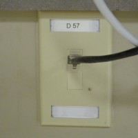
Standard Computer Wall Jack
The very common standard 8-pin computer wall jack. This wall jack is labeled “D-57” and physically connected to a patch panel in the network closet using Cat 5e Ethernet cable.
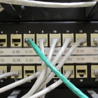
8-Pin Ports on Patch Panel in Network Closet
Patch panels in the network closets capture the back-end connections for all the IT devices in each building. Note that computer jack “D-57” shown above is terminated in Port 9 in this patch panel.
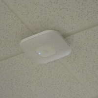
Wireless Access Point (AP)
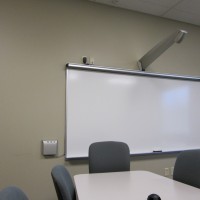
Wireless Access Points (AP’s) are actually connected back to a patch panel using Ethernet cable, much like any other IT device in the building. The “wireless” aspect simply refers to the communication between the AP and a wireless capable appliance such as a laptop computer. AP’s are unique because two of the 8-wires contained in the Ethernet cabling are used to power the AP device. The AP is physically connected to a patch panel in the network closet using Cat 5e Ethernet cable.Smart Projector
A smart projector similar to those that are being installed in Baldwin-Wallace’s new conservatory of music. Images can be captured on the screen, saved as files and passed through the IT infrastructure. This device, just like a wall jack, is connected to a patch panel in a network closet using Cat 5e Ethernet cable.
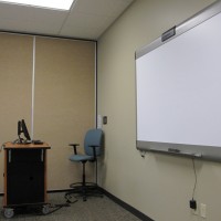
Media Cart and Smart Board
A media cart and smart board similar to those that are being installed in Baldwin-Wallace’s new conservatory of music. Smart boards allow class notes to be saved as files and sent through the IT system. These devices are also connected to a patch panel in a network closet using Cat 5e Ethernet cable, often through a wall jack or access panel in the floor.
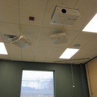
Ceiling Mounted Projectors
These ceiling mounted projectors are not smart -- the images they project cannot be saved, manipulated, or passed throughout the IT system. However, these projectors are also connected to a patch panel, and the status of their bulbs is monitored electronically via the IT system. Maintenance staff can monitor the projectors remotely and replace projector bulbs immediately.
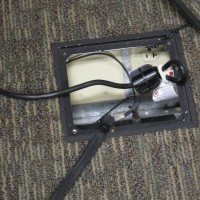
Access Panel in Floor
Media Carts plug into the IT system just like a wall jack, but usually through an access panel in the floor instead.
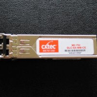
GBIC
Data signals are converted from metal wire (Cat 5e Ethernet) conductors to light signal-carrying (fiber optic patch cord) conductors using GBICs on the network switches.
Main Fiber Optic Cables
Single and multi-mode fiber optic cable leaving the buried conduit infrastructure at the floor of a network closet and terminating on a fiber optic patch panel.
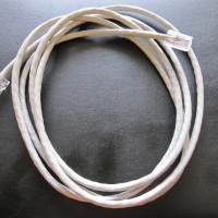
Category 5e Ethernet Cable
Used to connect all IT devices in the building to the patch panel in a network closet. This cable is also used to connect the patch panel to a network switch on the network closet rack. Contained within the insulation are eight separate wires, with an 8-pin jack on each end.
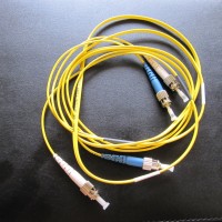
Fiber Optic Patch Cord
Used to connect a network switch to a fiber optic patch panel in a network closet.

Andrew Kimos
Andrew Kimos completed the civil engineering programs at the U.S. Coast Guard Academy (B.S. 1987) and the University of Illinois (M.S. 1992) and is a registered Professional Engineer in the state of Wisconsin. He served as a design engineer, construction project manager, facilities engineer, and executive leader in the Coast Guard for over 20 years. He worked as a regional airline pilot in the western U.S. before joining the Buildipedia.com team as Operations Channel Producer.
Website: buildipedia.com/channels/operations
