Light Gauge Metal Stud Framing
-
font size
decrease font size
 increase font size
Planning and Best Practices
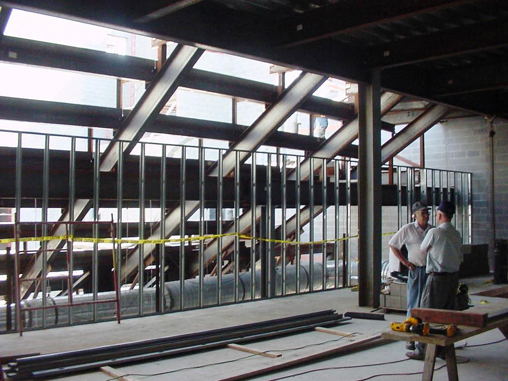
The light gauge metal stud framing phase of a project significantly impacts several other trades. It is no secret that good planning and practices will achieve higher production rates and a level of quality that meets the project's specifications. Planning and layout should be the responsibility of the project foreman; however, everyone should be involved with preparing the work flow. While actual layout is underway, other production items should also be thought through.
For example: arrange for a step ladder or get scaffolding set up, stock the area with correct materials, string out proper electric cords, set up an efficient place for the chop saw, and, if required, secure adequate lighting. These steps may seem inconsequential, but if they are not attended to beforehand and work has to stop so that someone can �go get it,� production is slowed down.
System Description
Non-Structural Metal Stud Reference Standards
American Society for Testing and Materials (ASTM):
- ASTM A653 / 653M Standard Specification for Steel Sheet, Zinc-Coated (Galvanized) or Zinc-Iron Alloy-Coated (Galvannealed) by the Hot-Dip Process. This specification covers steel sheet, zinc-coated (galvanized) or zinc-iron alloy-coated (galvannealed) by the hot-dip process in coils and cut lengths.
- ASTM C645 Specification for Nonstructural Steel Framing Members. This specification covers nonstructural steel framing members in interior construction assemblies.
- ASTM C754 Specification for Installation of Steel Framing Members to Receive Screw-Attached Gypsum Panel Product. This specification covers the minimum requirements for the installation of interior nonstructural steel framing and furring members designed to receive screw-attached gypsum panel products. The metal framing members noted in this specification are limited to those complying with ASTM C645 noted above.
- ASTM E488 Standard Test Methods for Strength of Anchors in Concrete and Masonry Elements. These test methods cover procedures for determining the static, seismic, fatigue and shock, tensile and shear strengths of post-installed and cast-in-place anchorage systems in structural members made of concrete or structural members made of masonry.
- ASTM E1190 Standard Test Methods for Strength of Power-Actuated Fasteners Installed in Structural Members. These test methods are intended to measure the anchoring capability and shear resistance of power-actuated fasteners to provide information from which applicable design values are to be derived for use in structural applications, such as in members of concrete, concrete masonry, and steel.
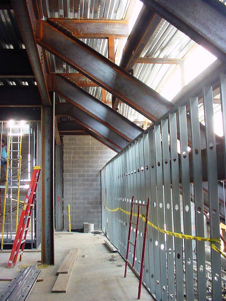
Non-load bearing or non-structural metal studs and framing are not designed or intended to carry any axial loads. Axial loads would include such elements as floor joists, ceiling joists, roof rafters, or roof trusses. They are, however, designed to carry the dead load of many typical wall finishes such as gypsum board, plaster work, or similar finishes, and to provide resistance to normal transverse loads. Lateral loads cannot exceed 10 lb/sq. ft on a steel framed wall system as defined by ASTM C645.
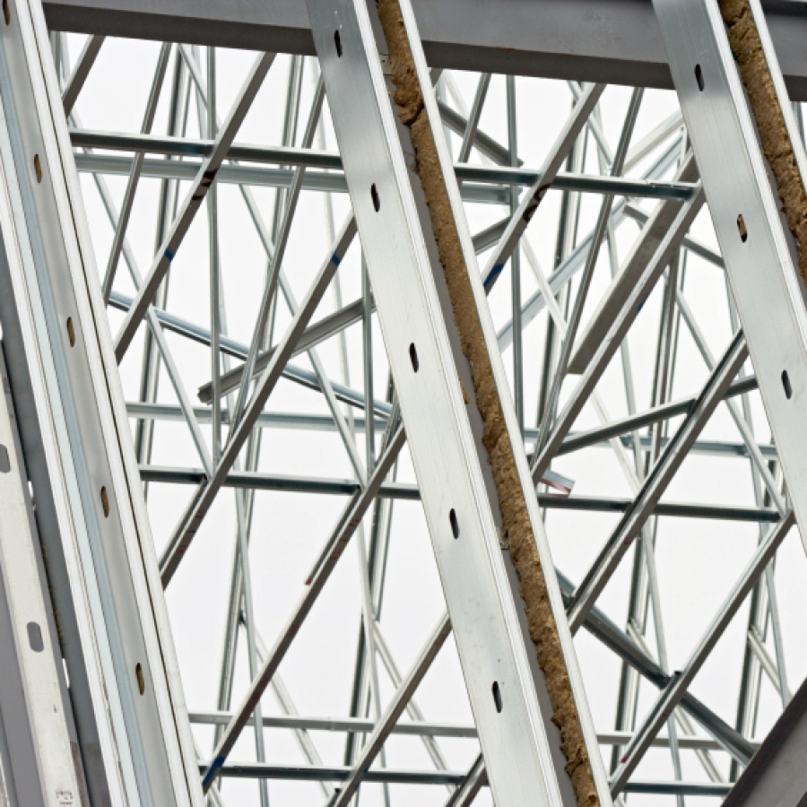
Light gauge metal framing used for interior wall partitions comes in�various shapes, thicknesses, sizes, and finishes. Each of these components has a specific function in the wall assembly. Selecting the correct size and thickness will depend primarily on the spacing of the framing members and the height of the wall. Center to center stud spacing for typical interior applications will either be 12", 16", or 24". Other considerations in the selection process include the makeup of the wall finishes, whether the wall finishes will be applied to one or both sides, and impact resistance requirements, if applicable. As a general rule of thumb, interior walls of a public space may require�more resistance to impact than do those of a private office.
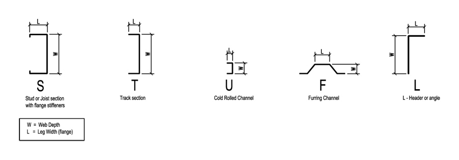
Typical Components of an Interior Wall System
- Studs (S)
- Tracks (T)
- U-Channels (U)
- Furring Channels (F)
- L-Headers (L)
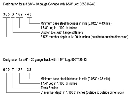
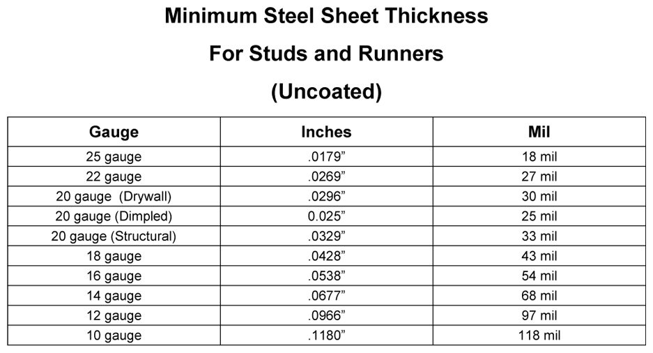
Metal studs are typically manufactured in lengths ranging from 8'-0" to 24'-0" and tracks which come�in 10'-0" lengths.� These are referenced by manufacturers with the acronym S T U F L. In addition to this acronym, other series of numbers are used to identify specific framing members, as shown in the gallery below. The smaller the gauge number the thicker and heavier the metal stud will be. See the Minimum Steel Sheet Thickness chart in the gallery below for a comparison of gauge numbers to actual metal thickness.

Tried and often used installation practices will enable other trades to be productive as well. The Steel Framing Alliance offers "A Builder�s Guide to Steel Frame Construction" on their web site. The following sections include best practices that apply to light gauge metal stud framing.
Track Layout
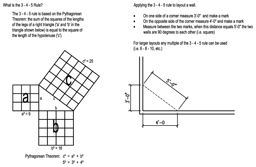
Clear floor area to a �broom clean� condition. It becomes important at this beginning stage of a project to measure the building for exactness, or at least be very close to the drawings. Should more than one contractor be �off� or not �square,� then corrections must be made early on, so as to not affect other rough-in trades. Following the contract drawings, measure the location of walls on the floor slab and chalk the lines to establish the top and bottom track positions. Square the lines using a 3 4 5 method as described in the gallery above.
Mark all locations of doors and wall openings at this time. A helpful hint is to coat the chalk lines with clear lacquer spray to keep the lines from being rubbed off by foot traffic. However, before proceeding with this method, verify with the floor finish schedule what the final finishes of the floors�are to be. It is�becoming common practice to avoid using a clear lacquer�if the floor is to remain exposed or be stained concrete. Layout lasers with horizontal and vertical lines are a tremendous aid, especially with longer walls. After establishing the layout, secure the bottom track with appropriate fasteners. Using a plumb line or laser with vertical line, layout the top track and secure it to the structure above with appropriate fasteners. Lasers with vertical lines are a tremendous aid in productivity and accuracy of track location. If not available, install a stud, then plumb, level, and secure the top track. When partitions extend to above the ceiling or to the deck, which is quite common in commercial buildings, studs can be installed in the bottom track, then friction fitted, plumbed, and attached to the top track. With this method diagonal bracing must be attached to the top track and secured to structure above.
�
Stud Layout
When starting to layout the bottom track to receive studs, an important item to consider is where the drywall will break. The term �break� refers to the location where one sheet of drywall will butt to the next. Since in most commercial projects the drywall is installed vertically, the joints will be at 4'-0". on center. To begin the layout, find the point where the first sheet will break, and start from there. The contract drawings will indicate the stud spacing to be 16� or 24� on center. Depending on the wall, a long straight demising wall or a short direction changing office wall, the first breaking stud may or may not be 4'-0". from your start point. A helpful hint is to clamp the tape measure to the track and pull layout from the first breaking stud. Layout can be marked at either the center of the stud or at the �soft side� (the open side) of the stud. It becomes very important to indicate to the crew which method is being used. Another item to be aware of is where the drywall will break at door and window openings. Many architects and specifiers do not allow for a joint at the door or window jamb, instead requiring the break to be above or below in the case of a window. If the layout does create an unacceptable condition, now is the time to adjust layout by moving the first breaking stud as required to correct the problem. Transferring the layout to the top track is a�relatively�simple task: install a stud on the layout mark, use a 4'-0" magnetic level to plumb the stud, clamp it in place, and fasten it to the track. The horizontal work reach is limited to the width of the scaffolding, so it is a good idea to layout and install the studs at the top track�at the same time.
�
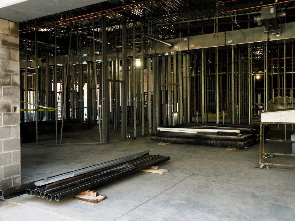
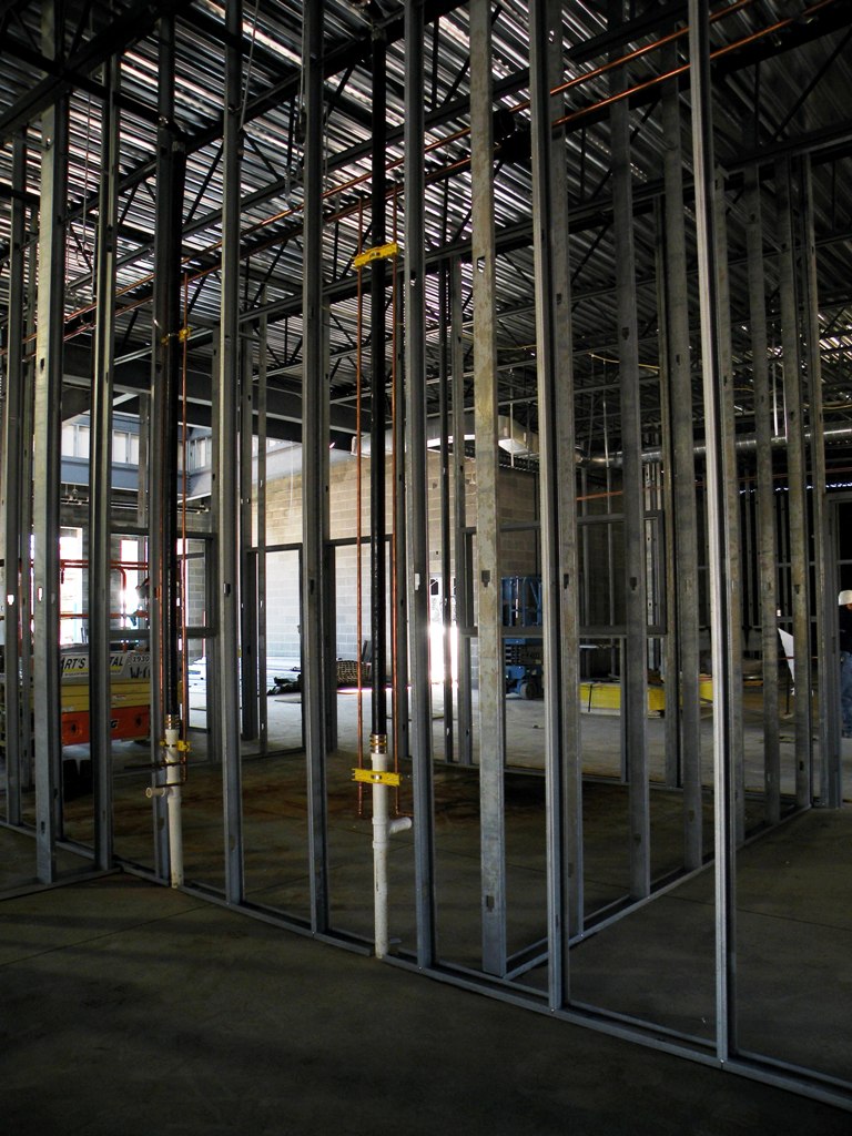
Installing Studs
 "Studding", "stuffing", or "framing" are just a few of the terms the framing crew may use to refer to installing studs. Installing the vertical studs is a fast and simple operation that seems to magically change the character of the project. The vertical framing is a three step process.
- Insert the studs diagonally into the bottom and top track.
- Slide the stud close to layout and twist into position with the soft side facing the direction from which the layout was pulled.
- Tap the stud into position, plumb with magnetic level, clamp and fasten to the track top and bottom on one side.
It should be noted here that there are several opinions on securing the studs to the tracks. Securing the stud on one side is more productive, keeps the stud in place during rough-in construction and allows the drywall hanger to unscrew the top and adjust the stud if need be to keep drywall on layout. The drywall on the other side will secure the stud at the tracks during installation. Some building inspectors will require the stud to be fastened at each side of the track. Although this is not required by ASTM, it is a good idea to be proactive and discuss this with the building inspector. This will prevent any loss of productivity and time.
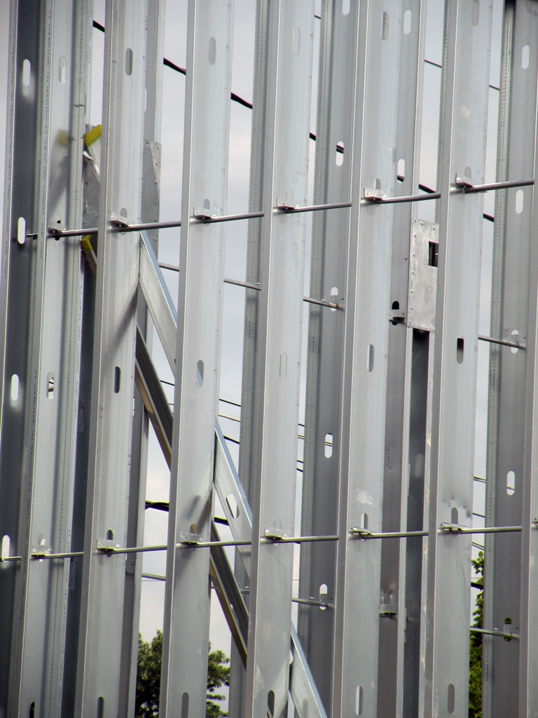
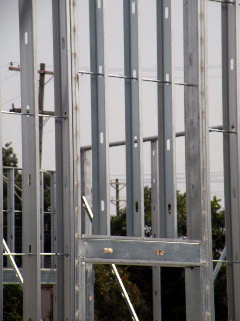
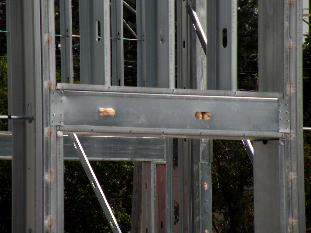
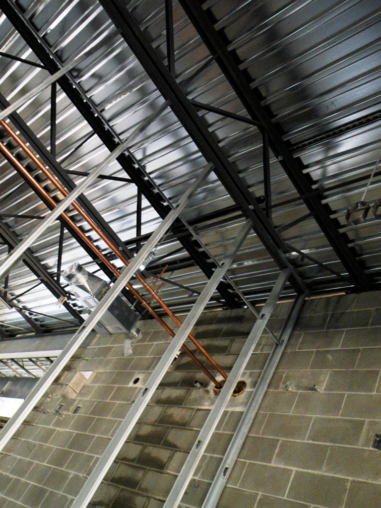
Orient the studs in the same direction and have the punch outs line up horizontally. This will be especially�important if horizontal bridging is specified. Plumbers and electricians will thank you. At this stage of framing, it is important to coordinate with the contract drawings to install all supplementary framing and blocking to support fixtures, equipment services, heavy trim, grab bars, handrails, toilet accessories, furnishings, or similar construction. In Figure 2, note the horizontal metal strapping for the future attachment of kitchen wall cabinets.

Other Common Components
Deflection tracks, headers and sills, and sliders are a few of the many construction elements common to metal stud framing.
A deflection track assembly is part of a wall construction assembly and is used to accommodate the expected vertical movement (deflection) of the structure without damage to the wall finish and system assembly. Two common methods include deep leg track and slip track.
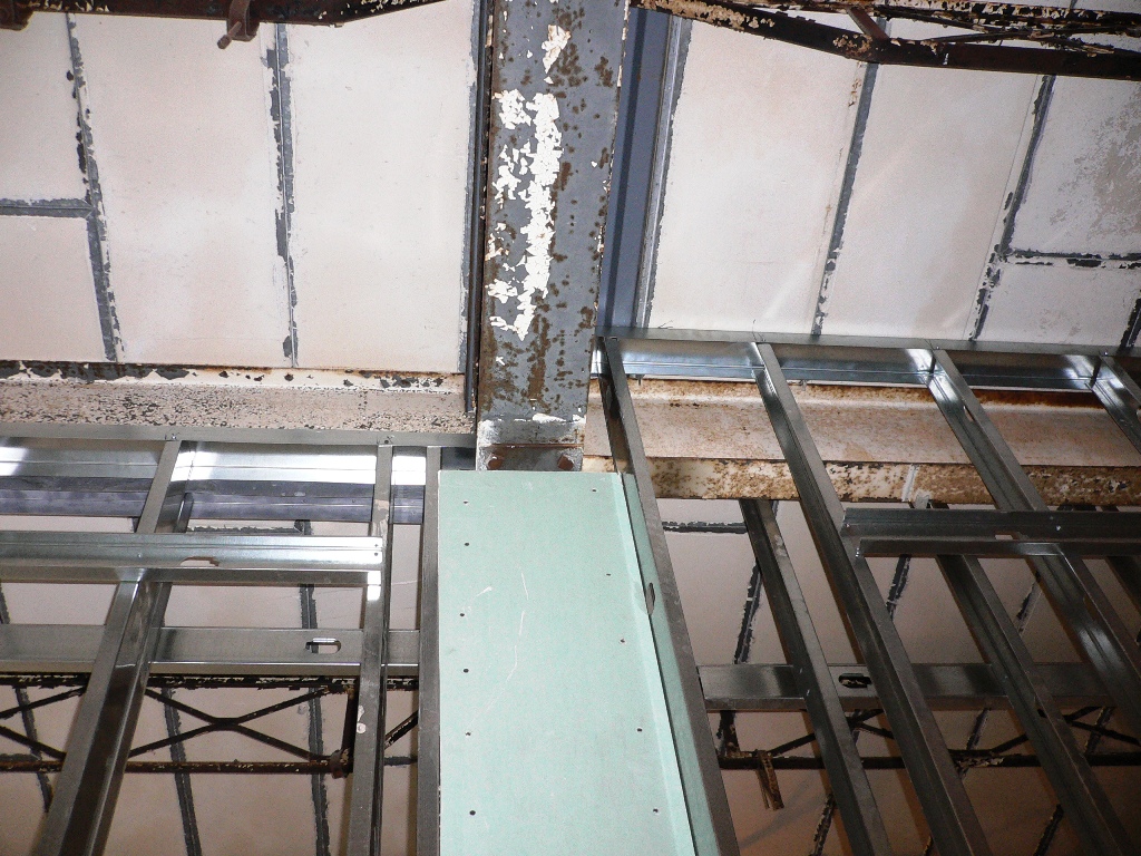
The deep leg track method is the simpler and faster of the two. This consists of a track with the vertical legs of 2� or more as shown in Figure 3. This track is installed the same as a slip track but the vertical studs are cut �� to 1� shorter and temporarily fastened in place. This fastener will be removed when the drywall is installed. Note: for deflection to occur without damaging the wall, the drywall must not be attached to the vertical legs of this track (see Figure 4).


The slider or slip track method consists of a two piece track system. The first track is oversized (compared to�stud width) by 1/8� and has 2� or more vertical legs which are secured to the structure. The second track is a normal track that fits inside the first. As with the deep leg method, vertical studs will have to be cut short and temporarily secured to the regular track. The temporary fastener will be removed when the drywall is hung, and with this system the drywall is held down below the oversized track. This method is effective, but it is also expensive and time consuming. As with most things in a labor intensive job, �necessity is the mother of invention,� and today there are many premanufactured deflection track systems available which will provide deflection if required. As an example, accordion style tracks are available which have a fold built in and have a deep leg track with screw slots which allow an up/down movement as well as clips that attach to studs and track to provide movement.
Headers and sills in non load bearing locations are simply fabricated by cutting a piece of track 6� to 12� longer than the opening. The track is centered in the opening with the excess cut at the vertical legs, and bent 90 deg. This U-shaped cap, shoe, or �dog ear� is then fitted over the vertical jamb studs and fastened at the correct head or sill height. Logically, the track will be installed up at the head and down at the sill to accept infill stud framing. Helpful hint: to keep the header/sill square across the hard side, cut one leg at the desired dimension square across the hard side, score with a utility knife, cut the other leg, and fold back. Manufacturers have not overlooked this construction item in creating premanufactured headers and sills. On large projects which involve a large number of similar sized openings (hotels, for example) premanufactured door or window headers can increase productivity and provide cost savings.
 Sliders, bypass locking, or slap studs are used to frame an inside corner where two walls intersect, instead of the common three piece or tri-corners. In this practice, the drywall slides by the 90 deg. wall and the stud in the corner is �slid to,� �slapped against� the bypassing drywall, and screwed in place creating a secure 90 degree corner as shown in Figure 5. Regardless of the layout direction of the studs, the slider is always fastened to the drywall through the hard side. This system will save two studs over conventional framing. Helpful hint: hold the slider stud back an inch or so and temporarily fasten it in place to prevent it from falling out; the drywall crew will unscrew it and slide the stud in place.
One of the newer �necessity inventions� of the last decade is the radius track or flex-track. Architects and designers are creating more unique and exciting spaces which may include curved walls, partitions, soffits or headers. This has created a challenge for the framing crews. It is very difficult to create these curved walls using standard framing materials. In the past, the legs of the track were notched with a chop saw or snips to form relief cuts. The track was then bent around a pattern on the floor. This was�very time consuming and expensive, requiring trial and error operation. Today the premanufactured flex-track has pre-determined relief cuts and moveable points on the hard side. Creating a radius is a simple matter of following the caulk line and securing to the floor. The top track is created the same way and, with the use of lasers to pinpoint the location, almost any shape is achievable. The same manufacturers that developed flex-track have also created a flexible angle product that allows the outside edge of a soffit to be curved.
There are many other framing practices, products, and tools that are available to the experienced framing carpenters who generally find the techniques that work best for them.
Light gauge metal stud framing can be labor intensive in comparison to the low cost of the materials. It is estimated that approximately 60% of the metal studs used in the United States are for interior non-structural wall partitions. Not only does light gauge metal framing offer durability, strength, and stability for wall partitions, it is also:
- Corrosion Resistant
- Fire Resistant
- Termite-proof
- Not susceptible to mold, and
- Made with recycled material
Best and acceptable framing practices, innovative steel framing products, and better tools are creating an environment which facilitates producing a quality project while still maintaining high production rates.
Related Content:

Contractor to Contractor: Installing Welded Hollow Metal Door Frames
In this installment of Rob Thimmes� series on framing walls with light gauge metal studs, he reviews the basics of hollow metal door frame installation.
During your framing process, the question of when you should set welded hollow metal door frames must be addressed. Many contractors prefer to install door frames before the walls are built. This facilitates the ease of fastening the �feet� down to the floor. After the frames are fastened down, braces are required to keep wind or inadvertent contact from toppling the freestanding frames. Read More...

Contractor to Contractor: Framing Out Openings
Contractor to Contractor: Follow professional interior contractor Robert Thimmes as he demonstrates how to frame-out openings. This third installment in a series of articles, Framing Walls With Light Gauge Metal Studs, visits the common practices for the framing of window and door openings. Read More...

Contractor to Contractor: Standing Up and Bracing Off Walls
Contractor to Contractor: Follow professional Interior Contractor Robert Thimmes as he demonstrates how to stand up and brace off walls. This second in a series of articles, Framing Walls With Light Gauge Metal Studs, starts with your walls located, lines chalked and bottom track already shot down (for details on this process, see Metal Stud Track Layout and Shoot-Down). Read More...

Contractor to Contractor: Metal Stud Track Layout and Shoot-Down
Contractor to Contractor: Follow professional Interior Contractor Robert Thimmes as he produces a layout and final shoot-down of a metal stud track system.
Plumb, level, square, and straight: all carpentry is the same, right? Well, no. Basic building principles apply, but how you build with metal studs differs greatly from building with wood. The following discussion offers a systematic explanation of installing metal studs, with various best practices for each step. Read More...


Mark Reisdorf
Mark graduated from Southern Illinois University in 1969 and, after a tour in the military, went to work for Marr Knapp and Crawfis Architects and Engineers in Mansfield, Ohio. Mark worked with the architectural firm from 1972 through 1985, receiving his Ohio Architectural Registration in 1984. While with the firm Mark was responsible for specifications and project site coordination. From 1985 through 2008 Mark was a partner with Quest Interior Construction Co., specializing in commercial light gauge metal stud framing, gypsum board systems, acoustical ceiling systems, hollow metal doors and frames, and flooring. As a project manager Mark was responsible for material and labor estimating, purchasing, and project management.