Case Study: BGSU Roof Replacement
-
font size
decrease font size
 increase font size
Video
alt=""Having provided 43 years of service, the Ice Arena at Bowling Green State University is a popular venue on campus that serves the BGSU students and faculty as well as the local municipal community. Currently operated by The Department of Recreation and Wellness, the Ice Arena was originally designed in 1965 and contains the main ice sheet, sized at 200� X 85�. It also houses a studio ice sheet that is 80� X 40� and a curling ice sheet at 150� X 57�, as well as a lounge and other supporting facilities.
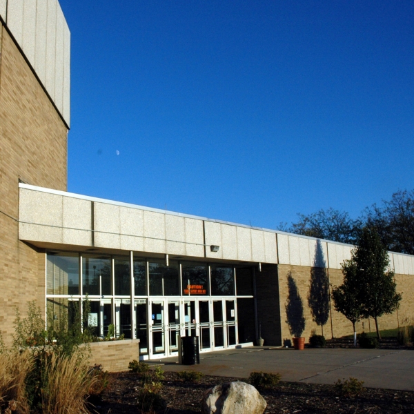 BGSU Ice Arena
David Ingold
BGSU Ice Arena
David Ingold
With the exception of a single story alumni hall addition on the northeast corner of the building and the installation of solar cells on the main roof, much of the original structure remains the same. There have been a few improvements to the interior over the years that included expanding permanent seating to the north end of the main ice, improving handicap accessibility, making lighting upgrades over the main ice, and making repairs and upgrades to the main ice and curling ice. Currently the arena seating capacity is at 5,000.
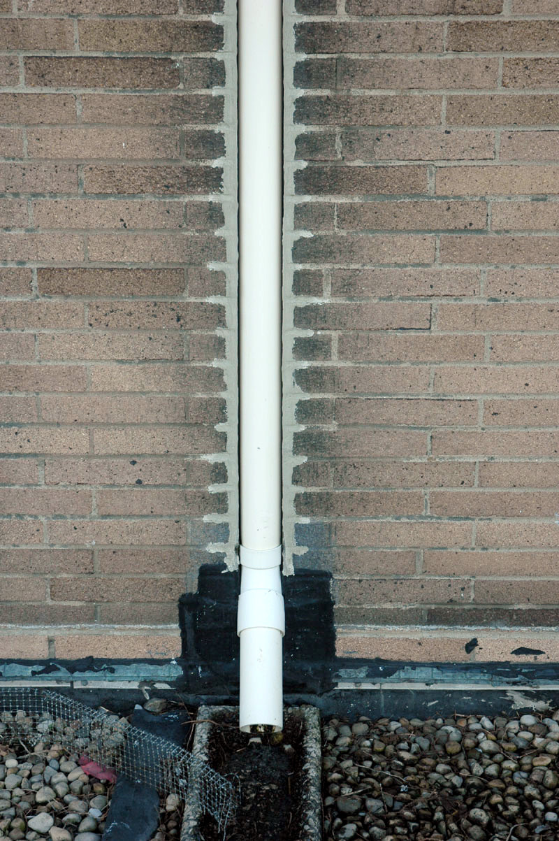
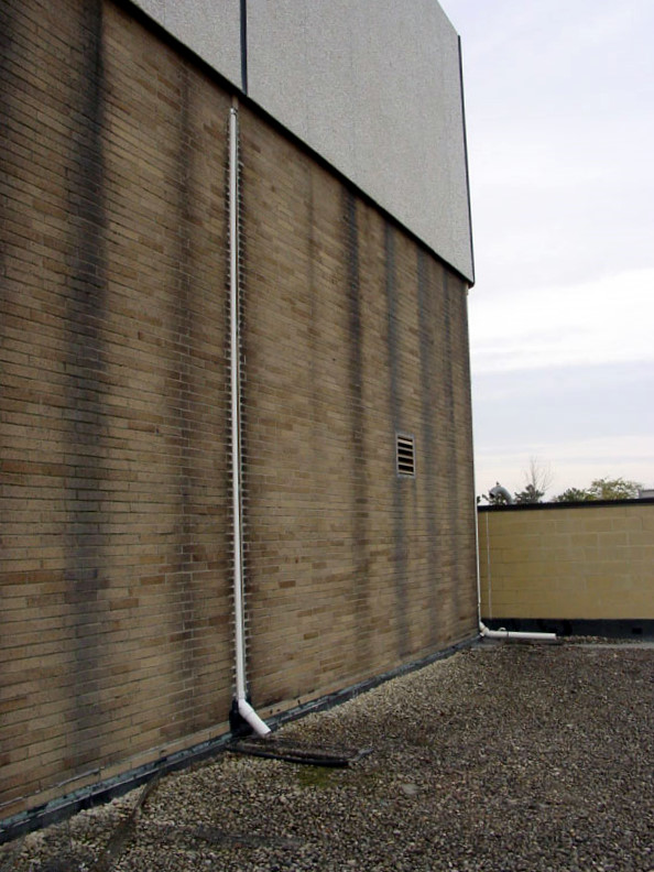
The ice arena features multiple roof elevations. The main roof, at almost 42 feet above grade, is quite unique in that the roof surface also makes up the top diaphragm of a 12�-6� deep truss system know as a Behlen truss. This deeply corrugated metal roof deck provides the necessary weather protection. However, the 830 lineal feet of built-in gutter system with integrated down spouts was undersized, and this has created problems for managing storm water discharge. The result has been water infiltration at various points along the wall. Modifications made over the years to try and correct this problem led to additional rain leaders being installed, and these leaders discharge a portion of the rain water volume to the lower roofs. This has only compounded the problem, however, and the extensive roof replacement project recently undertaken for the facility forms the basis for this case study.
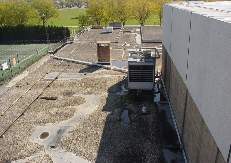
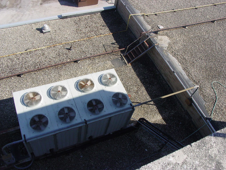 The lower roofs cover a single story structure; however, their elevations vary slightly from 6 inches to 42 inches. This lower roof area is currently being replaced as part of a larger scope of work. One of the major changes to be put into effect will be the installation of several new mechanical units, and these will need to be located on the lower roof.
This case study will provide some insight into the unique existing conditions at the BGSU Ice Arena, and discuss some of the challenges of integrating new efficient mechanical equipment and a superior roof replacement.
Existing Conditions and Issues
The existing ballasted membrane roof, base flashing and sealants all reached the end of their useful service life some time ago. Issues that needed to be addressed were many for this 20,000 square foot (1,858 square meter) roof. Numerous cracks and splits in the old roofing membrane and failed sealant joints have lead to repeated leaks throughout the facility. Early discussions with the owner and the facilities department reinforced the need for a complete roof system tear off and replacement. A brief description highlighting the existing conditions is as follows:
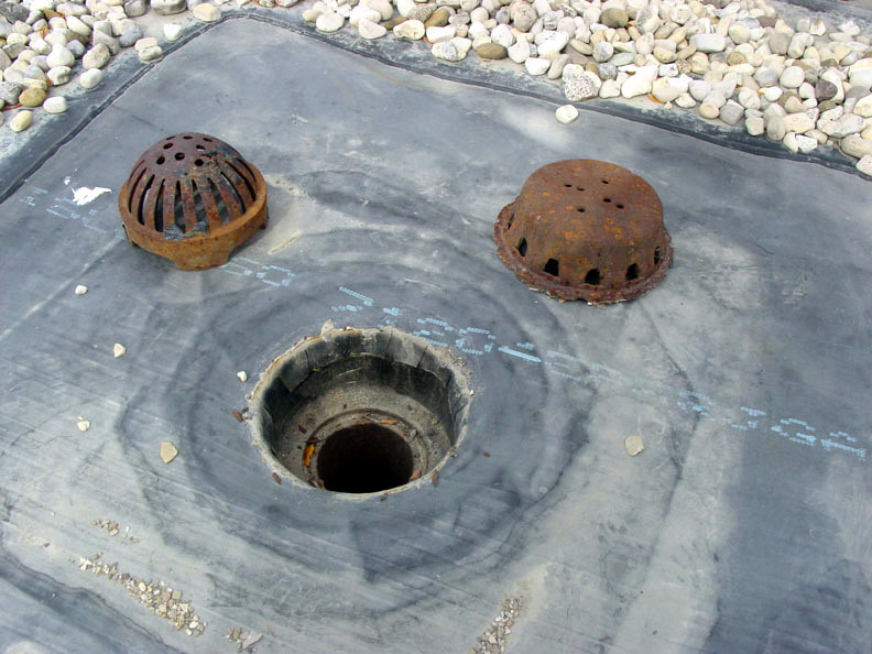
- As mentioned earlier, the additional volume of rain water from the upper roof is now being discharged to various areas of the lower roof. Therefore, the existing 4 inch diameter roof drains are too small to handle the water volume.
- The quantity of roof drains is also insufficient to handle the additional volume of rain water, and their locations are not ideal.
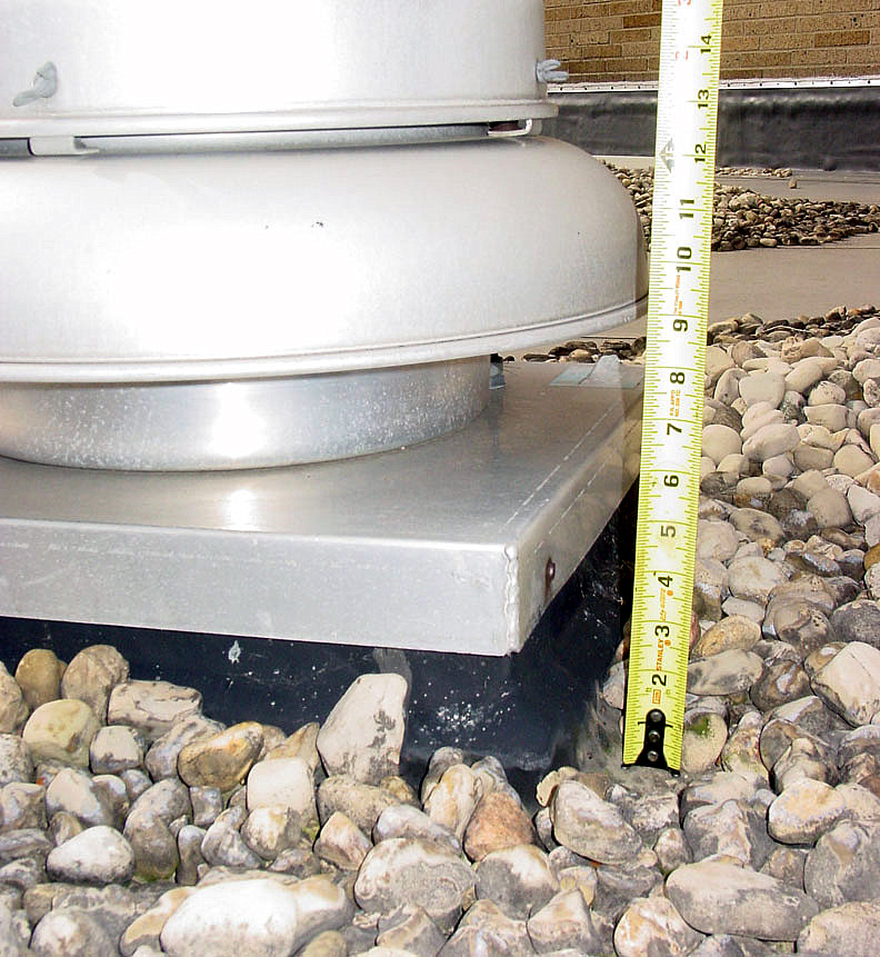
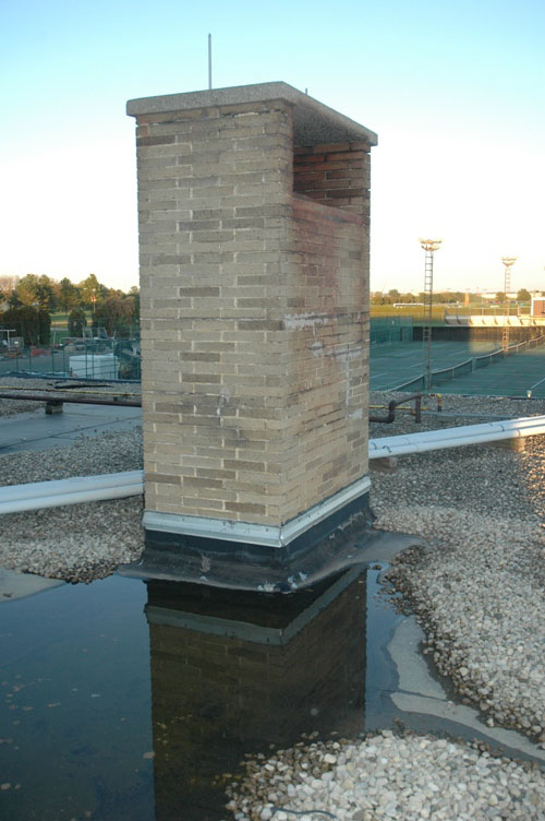
- The minimum flashing height is less than the recommended 8� at mechanical unit curbs, vents and most parapet wall locations.
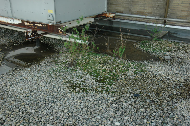
- The structural steel support frame for some mechanical equipment is less than 8� from the roof membrane. This creates less than desirable flashing conditions.
- There is insufficient roof slope to the drain, which leads to excessive ponding of water.
- The existing roof insulation has an insufficient R-Value.
- There are no provisions for secondary overflow drainage.
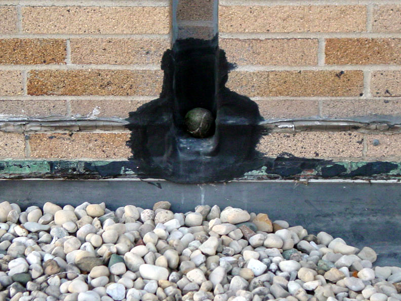
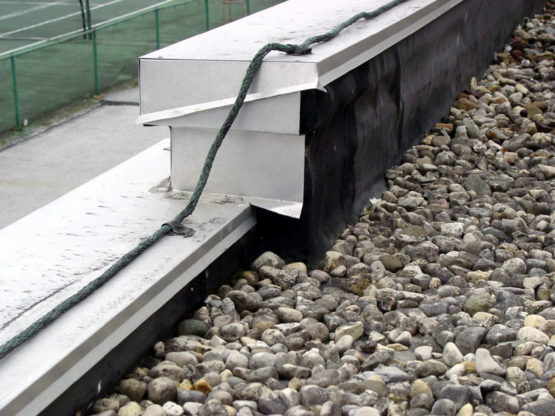
- Base flashing and roof edge flashing have experienced failure.
- There is excess roof deck deflection.
- There are multiple roof deck materials: 1 �� metal deck over bar joists, 7 �� deep metal deck supported by load bearing concrete masonry walls, 3� metal deck supported on load bearing concrete masonry walls, and 5� concrete deck supported on corrugated metal deck.
- Exhaust fan curbs and other mechanical curbs are too short for proper flashing.
- Multiple plumbing vent stacks do not protrude high enough to allow for adequate flashing.

Design Approach
Prior to beginning the design of a new roofing system, a complete survey of all existing conditions was conducted. It was important to complete several surveys and perform preliminary investigations to determine existing conditions and thus make recommendations for the scope of the roof replacement. All existing building elements needed to be accurately located and documented on the roof plan. Items such as mechanical equipment, equipment support systems, roof drains, plumbing vents, chimneys, service piping and curbs were located. All roof edge conditions were documented. Adjacent masonry walls were evaluated for their ability to resist moisture, and this was also documented. In this project, no test cuts or core samples were taken; it was previously determined that all insulation would be replaced as part of this project. The following brief narrative highlights each step of the design approach:
- Review all previous �As Built� construction drawings and verify their accuracy with field surveys and existing conditions.
- Calculate existing roof drain capacity to meet current codes. This now includes calculating one-half of the area of any vertical wall that diverts rainwater to the roof. This number needs to be added to the roof area for inclusion in calculating the required size of roof drain pipes.
- Eliminate the diverting of excess rain water from the upper roof to lower roofs.
- Remove roofing and insulation to existing roof deck.
- Replace roof drains and pans; connect to existing piping.
- Add minimum of 4� Polyisocyanurate Board Insulation, with the first layer mechanically fastened to the roof deck and subsequent layers set in adhesive.
- Add 1/8� per foot tapered insulation to provide positive drainage to each of the existing roof drains.
- Cover insulation with a �� thick glass-mat water-resistant gypsum cover board.
- Fully adhere 60 mil reinforced EPDM roofing membrane with matching sheet flashing.
- Maintain existing roof drain quantities if previous calculations will support this.
- Provide new flexible walkway pads to all new mechanical equipment.
- Add new roof access hatch.
- Replace roof deck as required by visual inspection or pull-out testing after roof tear-off is complete.
Design Challenges
The most significant design challenge will be to provide for several new large and heavy mechanical units. Some of the smaller units will be supported and mounted on mechanical curbs, while others will have a somewhat complicated structural steel framework that penetrates the roof. These units range from simple 3,000 pound Energy Recovery Ventilators (ERV) to 13,000 pound chillers, and include a 16,300 pound dehumidification air handling unit and a 15,200 pound air handling unit.
Another major challenge will be designing a tapered insulation system that will work with the existing roof drains. This will be paramount for the success of managing the rain water and eliminating any possibility of standing water. Significantly relocating or adding additional roof drains and associated rain leaders is not an option without increasing the scope of work and, thus, the construction budget. Additional design challenges are briefly highlighted below:
- Roof edge heights will need to be increased due to added tapered insulation.
- Plumbing vent stacks are too short.
- Mechanical unit curb heights are too short.
- There are no secondary roof drains or leaders.
- The lightening protection system will have to be removed and re-installed by a qualified contractor.
- There will have to be coordination of existing mechanical, electrical and plumbing equipment and service piping that is to remain.
- It will have to be verified that the roof structure is sufficient to support the maximum possible depth of water that will pond, as determined by the relative levels of new tapered insulation (assuming all drains were blocked and failed to operate).
- Construction loads on the roof must be limited to 100-lbs-per-wheel for rooftop equipment loads and 50 psf for uniformly distributed loads.
Design Summary
It is important to understand that all building components impinging upon the roof system need to be thoroughly understood and properly thought out and detailed. All penetrations, whether mechanical, electrical, plumbing, structural, or other, must be detailed to a large enough scale to clearly represent the design intent to the contractors. The new roof edges were clearly detailed to accommodate the increased height. All existing mechanical curbs were replaced with taller units to allow for a minimum of 8� of flashing. Existing plumbing vent stacks were replaced and extended to allow for proper flashing. Roof membrane enhancements, such as the fully adhered EPDM, assure that the roof system will have a long service life.


David Ingold
David Ingold is a graduate of The Ohio State University School of Architecture and a member of the Construction Specifications Institute (CSI) with Construction Documents Technology (CDT) certification. With more than 18 years of experience, David brings a broad knowledge base and understanding of design and construction to a wide variety of project types. He is an accomplished senior project administrator with experience in developing all phases of architectural documents. David has performed key responsibilities as a project leader, specifications writer, and coordinator for projects of all types and complexities including low- and high-rise condominiums, sporting facilities, higher education and government research laboratories, manufacturing facilities, wastewater treatment plants, parking garages, and campus master plans. David�s greatest aspiration� is to provide construction administrative services to fully execute project designs.
Website: buildipedia.com/channels/on-site